Switch-type peripheral charging circuit and charging system

A charging circuit and switching technology, applied in the field of switching peripheral charging circuits and charging systems, can solve the problems of long charging time, charging heat, low heat loss and the like

Pending Publication Date: 2021-03-26
GUANGZHOU CHICKEN RUN NETWORK TECH CO LTD
View PDF0 Cites 0 Cited by
  • Summary
  • Abstract
  • Description
  • Claims
  • Application Information

AI Technical Summary

Problems solved by technology

[0004] The invention provides a switch-type peripheral charging circuit and charging system, which are used to solve the problems of lo

Method used


Image

  • Switch-type peripheral charging circuit and charging system
  • Switch-type peripheral charging circuit and charging system
  • Switch-type peripheral charging circuit and charging system

Examples


Embodiment Construction

[0025] In order to make the purpose, technical solutions and advantages of the embodiments of the present invention clearer, the technical solutions in the embodiments of the present invention will be clearly and completely described below in conjunction with the drawings in the embodiments of the present invention. Obviously, the described embodiments It is a part of embodiments of the present invention, but not all embodiments. Based on the embodiments of the present invention, all other embodiments obtained by persons of ordinary skill in the art without creative efforts fall within the protection scope of the present invention.

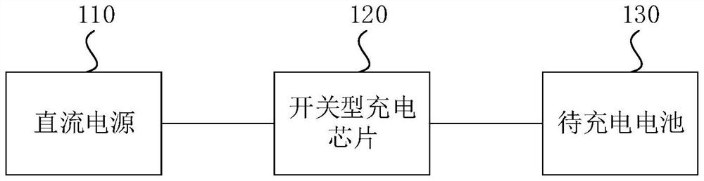
[0026] An embodiment of the present invention provides a schematic structural diagram of a switch-type peripheral charging system, figure 1 It is a schematic structural diagram of a switch-type peripheral charging system provided by an embodiment of the present invention. like figure 1 As shown, the switch-type peripheral charging circuit includ...


PUM


Abstract

The invention discloses a switch-type peripheral charging circuit and a charging system. The switch-type peripheral charging circuit comprises a switch-type charging chip. The input end of the switch-type charging chip is connected with a direct-current power supply, the output end of the switch-type charging chip is connected with a battery to be charged, and the switch-type charging chip is usedfor carrying out constant-current charging on the battery to be charged when the voltage of the battery to be charged is smaller than a constant-voltage threshold voltage of the switch-type chargingchip. And when the voltage of the battery to be charged is greater than or equal to the constant-voltage threshold voltage of the switch type charging chip, constant-voltage charging is performed on the battery to be charged. The battery to be charged is charged by adopting the switch type charging chip so that a charging heat loss can be effectively reduced, and the charging efficiency of the battery to be charged can be effectively improved. In addition, the phenomenon that the battery to be charged is overcharged due to the fact that the battery to be charged is fully charged can be avoided, and therefore the use loss of the battery to be charged is reduced.

Description

technical field [0001] The embodiments of the present invention relate to the technical field of circuit design, in particular to a switch-type peripheral charging circuit and a charging system. Background technique [0002] As the demand for wireless portable products in the market becomes stronger and stronger, the types of wireless portable products become more and more abundant, and users use more and more wireless portable products. Since it is not convenient for the user to carry a power source when traveling, it is inconvenient to design wireless portable products as a way of connecting the power supply with wires, and most of the wireless portable products are designed to have a rechargeable battery for independent power supply, resulting in wireless portable products. There is an increasing demand for charging efficiency in large-capacity rechargeable batteries. [0003] At present, circuit designers use linear low dropout regulator (LDO) charging chips to charge b...

Claims


Application Information

Patent Timeline
IPC IPC(8): H02J7/00
CPCH02J7/00302H02J7/007182
Inventor 马尧林骏朱庭树戴经佩
Owner GUANGZHOU CHICKEN RUN NETWORK TECH CO LTD
Why Eureka
Try Eureka