Channel transmission method and communication equipment

A communication equipment and channel transmission technology, applied in the field of communication, can solve the problem of large downlink control channel propagation delay and other problems

Active Publication Date: 2021-03-26
DATANG MOBILE COMM EQUIP CO LTD
View PDF5 Cites 5 Cited by
  • Summary
  • Abstract
  • Description
  • Claims
  • Application Information

AI Technical Summary

Problems solved by technology

[0006] The embodiment of the present invention provides a channel transmission method and communication equ

Method used


Image

  • Channel transmission method and communication equipment
  • Channel transmission method and communication equipment
  • Channel transmission method and communication equipment

Examples


Embodiment 1

[0125] It is assumed that the power saving signal (PS) is carried by the PDCCH. The network side device configures a search space SS#L for the PDCCH carrying PS (PS-PDCCH), and the CORESET associated with the SS#L is CORESET#B, that is, SS#L needs to be transmitted in CORESET#B. The network side device does not configure any TCI state for CORESET#B. The period of SS#L is configured as 1 slot, and the listening window of the PS-PDCCH is configured as W by the network side device. In this embodiment, W=5, that is, 5 slots. There are Q SSBs in the system. In this embodiment, Q=4, that is, the SSBs sent by the network side device are {SSB#1, SSB#2, SSB#3, SSB#4}.

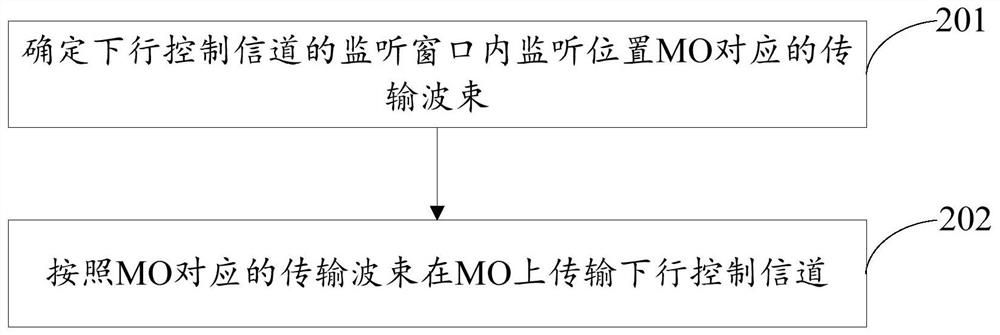
[0126] The terminal and the network side device determine the transmission beam corresponding to each MO in the PS-PDCCH listening window according to predefined rules, specifically, the transmission beam corresponding to the i-th MO is determined by the SSB numbered j, j=mod(i, Q), that is, the beam direction of the ...

Embodiment 2

[0130] As described in Embodiment 1, the listening window of the PS-PDCCH is a predefined listening window.

Embodiment 3

[0132]It is assumed that the energy saving signal is carried by the PDCCH. The network side device configures a search space SS#L for the PDCCH carrying PS (PS-PDCCH), and the CORESET associated with the SS#L is CORESET#B, that is, SS#L needs to be transmitted in CORESET#B. The network side device does not configure any TCI state for CORESET#B. The period of SS#L is configured as 1 slot, and the listening window of the PS-PDCCH is configured as W by the network side device. In this embodiment, W=10, that is, 10 slots. There are Q SSBs in the system. In this embodiment, Q=4, that is, the SSBs sent by the network side device are {SSB#1, SSB#2, SSB#3, SSB#4}.

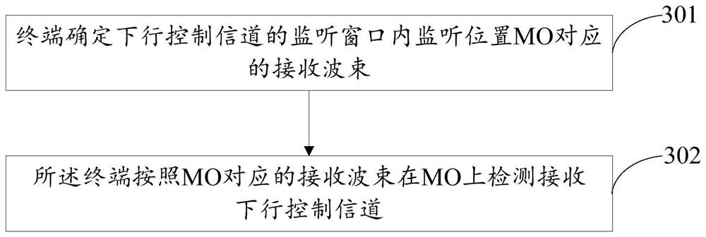
[0133] The network side device indicates the sending and receiving beams corresponding to each MO in the PS-PDCCH listening window through high-level signaling, for example, through RRC signaling, SIB1, OSI or MAC CE. Specifically, the network side device indicates through high-level signaling that the beam corresponding...


PUM


Abstract

The embodiment of the invention provides a channel transmission method and communication equipment. The method comprises the following steps: determining a transmission beam corresponding to a monitoring position MO in a monitoring window of a downlink control channel; and transmitting the downlink control channel on the MO according to the transmission beam corresponding to the MO. Thus, when thetransmission beam changes, the propagation delay of the downlink control channel can be reduced, and the transmission reliability of the downlink control channel can be improved.

Description

technical field [0001] The present invention relates to the technical field of communication, in particular to a channel transmission method and communication equipment. Background technique [0002] In a communication system, when using some frequency bands (such as FR2 frequency band, where FR2 frequency band refers to a frequency band with a frequency greater than 6 GHz) for transmission, it is required that the terminal and the network side device have a consistent understanding of the transmission beam. At present, there are many ways to determine the transmission beam. For example, the terminal determines its associated SSB (Synchronization signal Block, synchronization signal block) during the cell search (cell search) process, and detects and receives the downlink at the position corresponding to the receiving beam in the subsequent detection. For the control channel, the terminal can track the beam through the beam management (beam management) process, and obtain a ...

Claims


Application Information

Patent Timeline
IPC IPC(8): H04B7/06
CPCH04B7/0617H04W52/0216H04W52/0229H04L5/0053H04L5/0023H04B7/0695H04B7/086H04W72/23
Inventor 王磊王加庆
Owner DATANG MOBILE COMM EQUIP CO LTD
Why Eureka
Try Eureka