Single-Level Parallel-Gated Carry/majority Circuits and Systems Therefrom

a single-level, parallel-gated carry technology, applied in the field of numerical data processing, can solve the problems of limiting commercial applications that require lower power implementation, circuits were complex, and extra levels translated into unnecessary power consumption in registers, and achieves lower propagation delay and higher clock rate

Inactive Publication Date: 2007-09-06
BAE SYST INFORMATION & ELECTRONICS SYST INTERGRATION INC
View PDF16 Cites 2 Cited by
  • Summary
  • Abstract
  • Description
  • Claims
  • Application Information

AI Technical Summary

Benefits of technology

[0020] According to one embodiment, all of the inputs of the carry circuit are on the same level allowing a lower propagation delay and higher clock rates in high speed accumulators.

Problems solved by technology

The power consumption of the registers becomes a dominant factor for accumulators with large bit-widths, thus limiting commercial applications that demand lower power implementations.
In the general pipelined adder-accumulators, the circuits were complex because numerous latches were required for synchronization between stages.
Unless multiple power supplies are utilized, the extra levels translate into unnecessary power consumption in the registers.
The problems associated with having multiple power supplies for the design with carry and sum circuits both requiring four series-gated levels, while registers only requiring two series-gated levels was heretofore unresolved.
While carry / majority circuits are generally known, there are also known limitations with respect to speed and power requirements.

Method used


Image

  • Single-Level Parallel-Gated Carry/majority Circuits and Systems Therefrom
  • Single-Level Parallel-Gated Carry/majority Circuits and Systems Therefrom
  • Single-Level Parallel-Gated Carry/majority Circuits and Systems Therefrom

Examples


Embodiment Construction

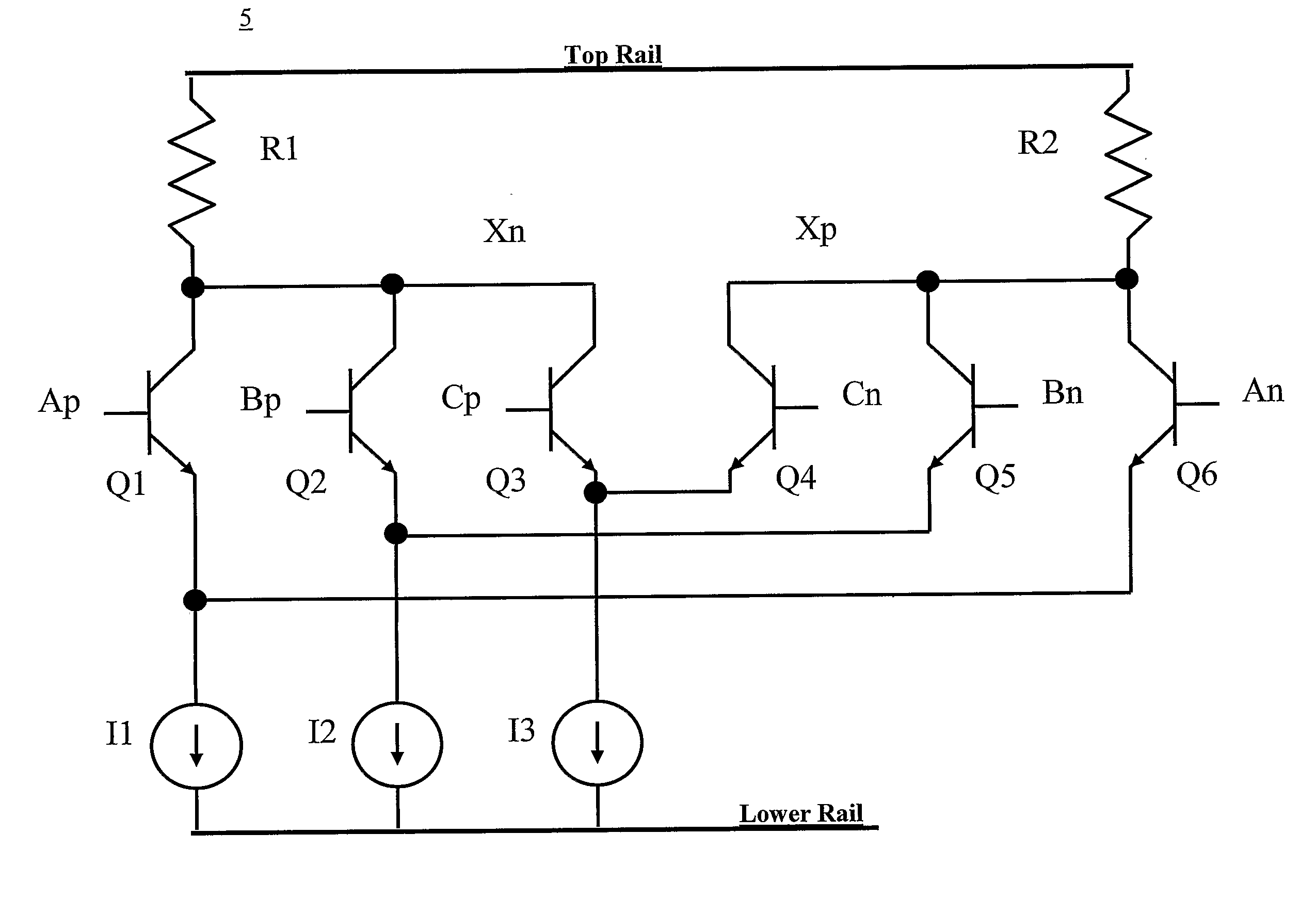
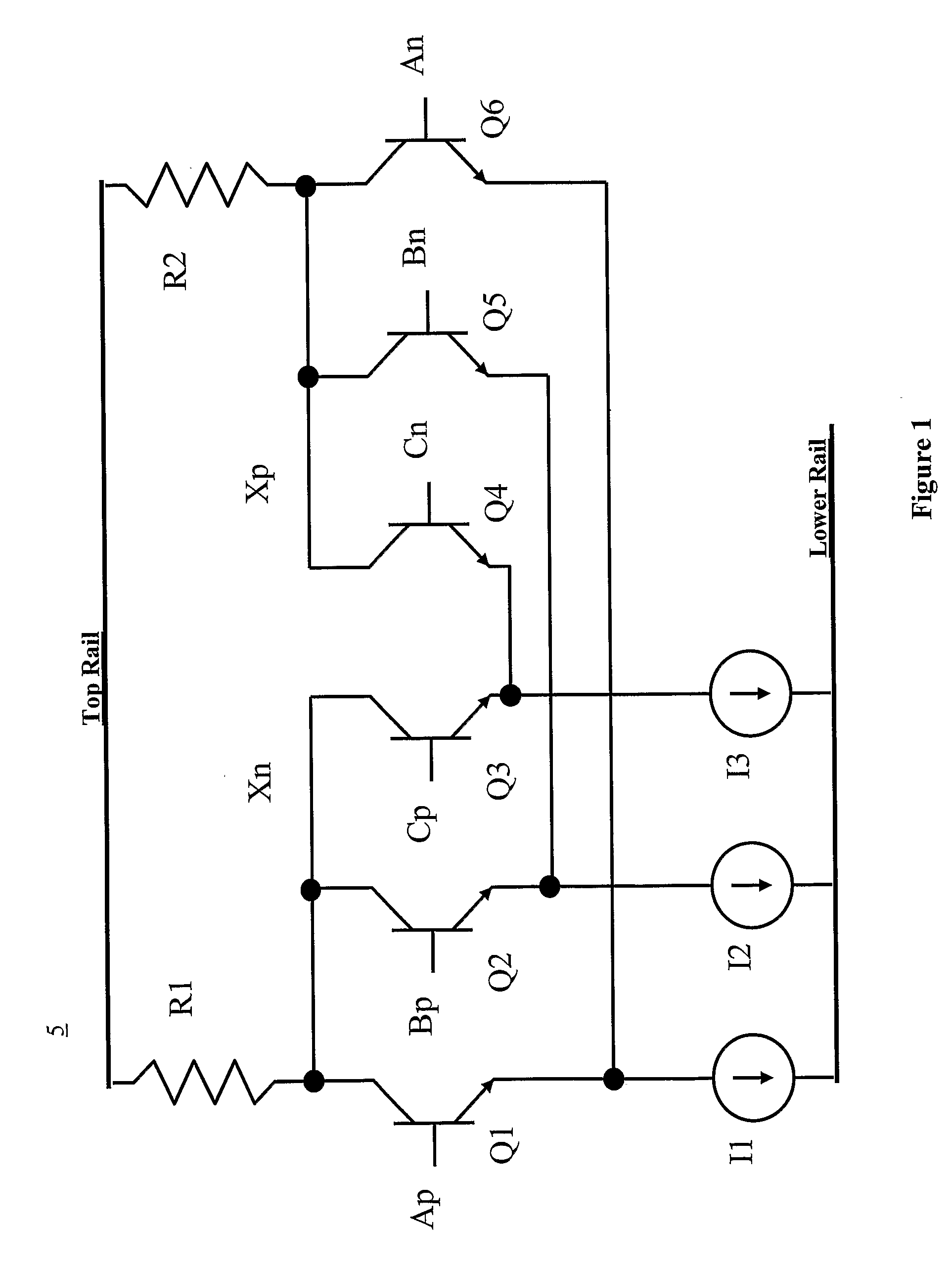
[0033] The circuit of FIG. 1 is a carry / majority circuit 5 that detects when two or three of the inputs are high. The circuit in this embodiment relies on differential emitter coupled logic (ECL) and it has three identical differential pairs, however the implementation in ECL is not a limitation as other technologies can be employed. The differential pair inputs in this example have inputs illustrated as Ap / An, Bp / Bn, and Cp / Cn. These differential pair inputs are respectively coupled to differential pairs Q1 / Q6; Q2 / Q5; and Q3 / Q6. The present system steers current through the leg of the circuit with the higher differential, wherein the current through the leg is represented as I1, I2 and I3 respectively for each differential pair. For each differential pair, the current is steered through the transistor with the higher input voltage.

[0034] There is a Top Rail coupled to the other end of the resistors R1 / R2 that may be coupled to ground or a voltage supply depending upon the design. ...


PUM


Abstract

A carry / majority circuit, comprising a plurality of differential transistor pairs coupled in parallel and forming a pair of output nodes, with a single parallel gated level. Current is steered through a leg of the transistor pair having a higher input voltage.

Description

RELATED APPLICATIONS [0001] This application claims the benefit of U.S. Provisional Applications No. 60 / 585,719, filed Jul. 6, 2004, and 60 / 585,632 filed Jul. 6, 2004. Each is incorporated in its entirety by reference.STATEMENT OF GOVERNMENT INTEREST [0002] Portions of the present invention may have been made in conjunction with Government funding under contract DAAD17-02-C-0115, and there may be certain rights to the Government.FIELD OF THE INVENTION [0003] The present invention relates generally to the processing of numerical data and more particularly to circuit designs for arithmetic processing. BACKGROUND OF THE INVENTION [0004] Underlying advanced digital processing systems are smaller basic digital circuit building blocks. The simple building blocks are combined and arranged in such a manner as to provide extremely fast and sophisticated processing. [0005] A carry circuit is typically used in arithmetic units, such as adder or subtractors, to process a carry operation in orde...

Claims


Application Information

Patent Timeline
Patent Type & Authority Applications(United States)
IPC IPC(8): G06G7/00
CPCH03K19/23H03K19/21
Inventor TURNER, STEVEN
Owner BAE SYST INFORMATION & ELECTRONICS SYST INTERGRATION INC
Why Eureka
Try Eureka