High-speed and high-precision phase locked loop

a phase lock loop, high-speed technology, applied in pulse automatic control, multi-input and output pulse circuits, electrical apparatus, etc., can solve the problems of phase frequency detector including a conventional static logic gate structure, speed limitation, jitter in the clock output, etc., to reduce the propagation delay through the detector, less jitter, and high precision

Inactive Publication Date: 2005-08-16
SUPER INTERCONNECT TECH
View PDF7 Cites 2 Cited by
  • Summary
  • Abstract
  • Description
  • Claims
  • Application Information

AI Technical Summary

Benefits of technology

[0006]The present invention provides a phase lock loop that includes a dynamic phase frequency detector that includes dynamic logic, instead of static logic, to decrease the propagation delay through the detector.
[0007]The dynamic phase frequency detector increases the maximum operating frequency of the PLL with higher precision and less jitter at the PLL output clock. The dynamic phase frequency detector is simpler. The number of transistors and the layout area is reduced for an efficient implementation. As a result, the conventional static phase frequency detector is replaced by the dynamic phase frequency detector for high precision and low jitter operation of PLL.

Problems solved by technology

First, the supply noise can abruptly change the frequency of the VCO and result in PLL clock output jitter.
A low precision of phase frequency detector typically has a large minimum detectable phase difference (or “dead zone”), which increases the jitter.
A phase frequency detector including a conventional static logic gate structure has a speed limitation due to the propagation delay through multiple logic gate stages.
This speed limitation increases the dead zone in the operation of the phase frequency detector at high frequency, and hence increases the jitter.

Method used


Image

  • High-speed and high-precision phase locked loop
  • High-speed and high-precision phase locked loop
  • High-speed and high-precision phase locked loop

Examples


Embodiment Construction

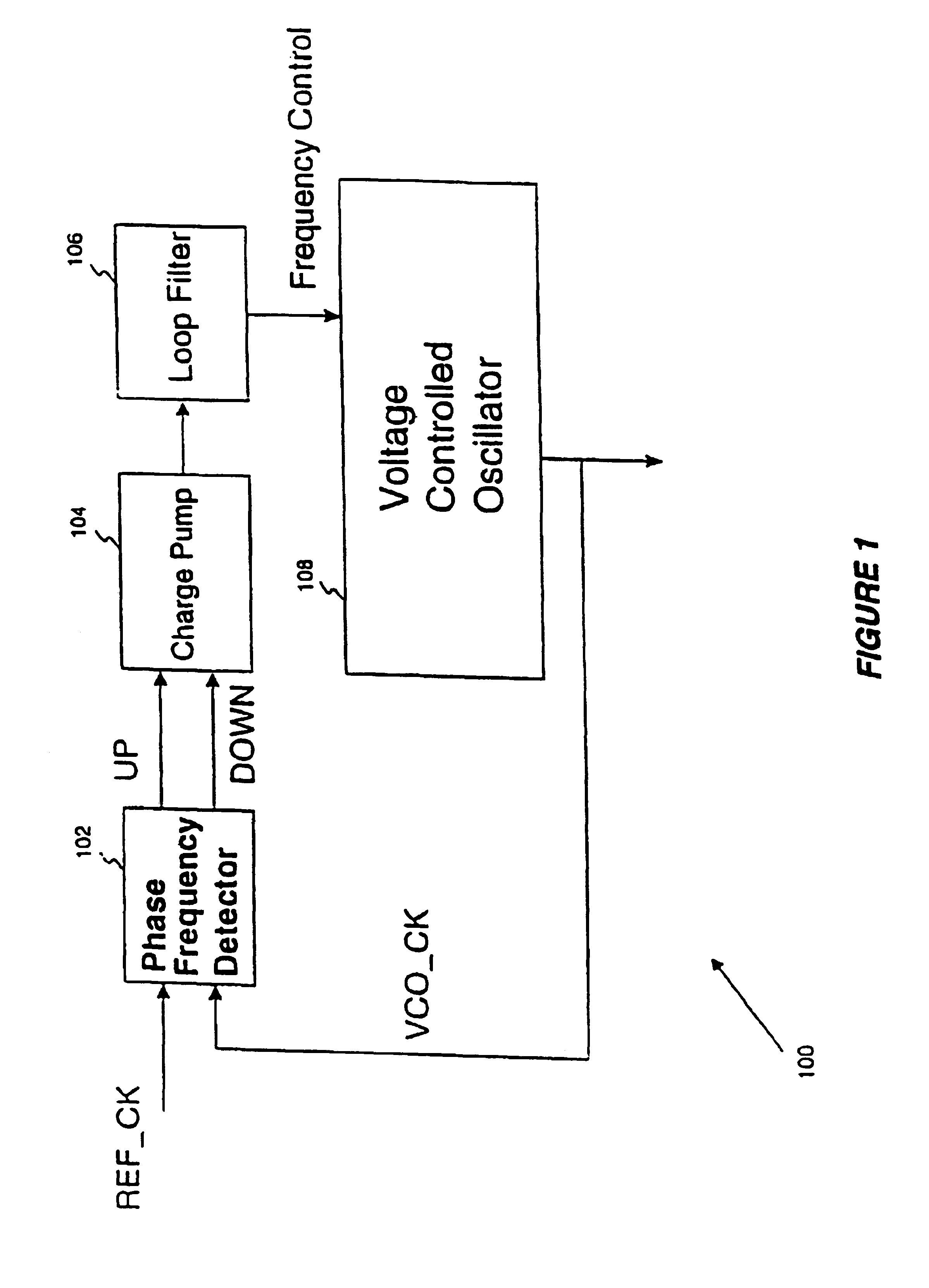
[0021]Referring to FIG. 1, there is shown a block diagram illustrating a phase lock loop (PLL) circuit 100, which includes a phase frequency detector 102, a charge pump 104, a loop filter 106, and a voltage controlled oscillator (VCO) 108. A reference clock signal and a VCO clock signal from the VCO 108 are applied to respective input terminals of the phase frequency detector 102. The phase frequency detector 102 compares the phase of the reference clock signal and the VCO clock signal and provides an up signal and a down signal to respective input terminals of the charge pump 104. The up and down signals indicate respective positive and negative charge directions for the charge pump 104 to provide a voltage control signal to the VCO 108 for varying the frequency of the oscillation signal or VCO clock signal from the VCO 108.

[0022]The phase frequency detector 102 generates the phase difference between the up and down signals to be substantially equal to the phase difference between ...


PUM


Abstract

A phase lock loop includes a charge pump, a voltage controlled oscillator (VCO), and a phase frequency detector. The phase frequency detector has a dynamic logic structure. The phase frequency detector generates up and down signals for directing the charge pump to provide a voltage signal to the VCO to vary the frequency of the VCO clock. The difference between the up and down signals is indicative of the phase difference between the reference clock signal and the VCO clock. The phase frequency detector includes up and down signal generators for generating the up and down signals, respectively.

Description

CROSS REFERENCE TO RELATED APPLICATIONS[0001]This is a continuation of application Ser. No. 09 / 098,266 which was filed on Jun. 16, 1998, now U.S. Pat. No. 6,157,263 and which is specifically incorporated herein by reference. This is also a continuation of Ser. No. 09 / 693,516 Oct. 20, 2000 U.S. Pat. No. 6,462,624 and CON of Ser. No. 08 / 631,420 Apr. 12, 1996 U.S. Pat. No. 5,815,041FIELD OF THE INVENTION[0002]This invention relates to phase-lock loop circuits, and more particularly to high speed and high-precision phase frequency detectors.BACKGROUND OF THE INVENTION[0003]Phase lock loops (PLL) typically include a phase frequency detector (PFD) that provides control signals indicative of a phase difference between a reference clock and an oscillation signal or a VCO clock of a voltage controlled oscillator (VCO). A charge pump provides a voltage signal to the VCO in response to the control signals. The VCO provides the oscillation signal responsive to the voltage signal.[0004]As the fr...

Claims


Application Information

Patent Timeline
Patent Type & Authority Patents(United States)
IPC IPC(8): H03L7/08H03L7/089H03K5/26
CPCH03L7/0891H03L7/089
Inventor LEE, KYEONGHOJEONG, DEOG-KYOON
Owner SUPER INTERCONNECT TECH
Why Eureka
Try Eureka