Oscillator comprising an RC-circuit and a push-pull stage and electronic device comprising the oscillator

a technology of oscillator and push-pull stage, which is applied in the direction of pulse generator, pulse technique, electrical apparatus, etc., can solve the problems of limited clock signal clk of oscillator b>2/b>, not fully integrated, and requiring a larger space, so as to reduce propagation delay

Inactive Publication Date: 2013-12-19
TEXAS INSTR INC
View PDF4 Cites 3 Cited by
  • Summary
  • Abstract
  • Description
  • Claims
  • Application Information

AI Technical Summary

Benefits of technology

[0006]In the oscillator, according to aspect of the invention, the voltage divider and comparator (in comparison to the prior art) is replaced by the two complementary transistors which are for; example, field effect transistors (FETs). This reduces the propagation delay, and accordingly, an oscillator for providing a clock signal having a frequency of 20 MHz or higher may be provided. The oscillator is a fully integrated oscillator and there is no need for an LC-circuit or a comparator.

Problems solved by technology

However, the frequency of the clock signal CLK of the oscillator 2 (according to the prior art) is limited due to the propagation delay of the comparator 8.
Alternatively, an LC oscillator may be applied which; however, is not fully integrated and requires larger space.

Method used


Image

  • Oscillator comprising an RC-circuit and a push-pull stage and electronic device comprising the oscillator
  • Oscillator comprising an RC-circuit and a push-pull stage and electronic device comprising the oscillator
  • Oscillator comprising an RC-circuit and a push-pull stage and electronic device comprising the oscillator

Examples


Embodiment Construction

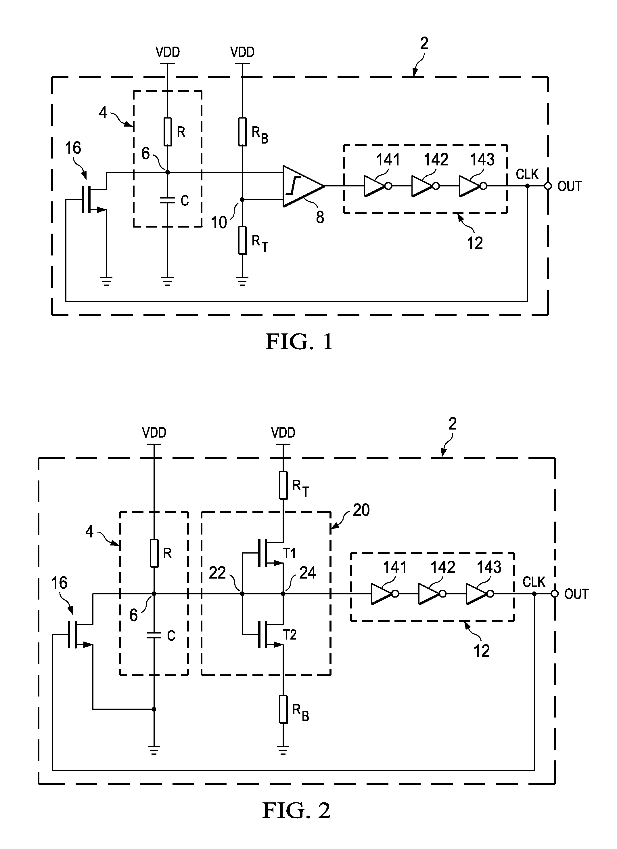
[0017]FIG. 2 is a simplified circuit diagram of an oscillator 2 comprising an RC-circuit 4, a push-pull stage 20, an inverter stage 12 and a switching transistor 16. The RC-circuit comprises a resistor R and a capacitor C coupled in series between a high supply voltage line; for example, VDD, and a low supply voltage line, which may be coupled to ground according to the embodiment of FIG. 2. A tapping point 6, which is located between the resistor R and the capacitor C of the RC-circuit 4, is coupled to an input node 22 of the push-pull stage 20.

[0018]The push-pull stage 20 comprises a first transistor T1 and a second transistor T2, wherein the channel of the first transistor T1 and the channel of the second transistor T2 are coupled in series between the high supply voltage line (VDD) and the second supply voltage line (ground). Between the channel of the first transistor T1 and the channel of the second transistor T2, there is an output node 24 of the push-pull stage 20. The outpu...


PUM


Abstract

Oscillator and electronic device comprising an oscillator, wherein the oscillator has an RC-circuit and a push-pull stage. A tapping point of the RC-circuit is coupled to an input of the push-pull stage and an output of the push-pull stage is fed back to a switching transistor which is coupled to the tapping point of the RC-circuit.

Description

FIELD OF THE INVENTION[0001]The invention relates to an oscillator comprising an RC-circuit coupled between a high supply voltage line and a low supply voltage line and a push-pull stage coupled to the RC-circuit. Further, the invention relates to an electronic device comprising the oscillator.BACKGROUND OF THE INVENTION[0002]Oscillators are widely used; for example, for clock generation purposes in electronic devices. Fully integrated oscillators (according to the prior art) use a voltage divider combined with an RC-coupled comparator to generate the clock signal. An oscillator (according to the prior art) is shown in the simplified circuit diagram of FIG. 1. The oscillator 2 comprises an RC-circuit 4 having a resistor R and a capacitor C coupled in series between VDD and ground. A tapping point 6 between the resistor R and the capacitor C is coupled to a first input of a comparator 8. A second input of the comparator 8 is coupled to a voltage divider comprising a first resistor RB...

Claims


Application Information

Patent Timeline
Patent Type & Authority Applications(United States)
IPC IPC(8): H03K3/26
CPCH03K3/0231
Inventor COULEUR, MICHAELGUENTHER, STEFAN
Owner TEXAS INSTR INC
Why Eureka
Try Eureka