Transimpedance amplifier

a trans-impedance amplifier and amplifier technology, applied in amplifiers, light-controlled amplifiers, electrical equipment, etc., can solve the problems of increasing the potential of output propagation delay from high to low, and the inability to achieve high sensitivity, so as to reduce the propagation delay of trans-impedance amplifiers and improve the stability of reference voltage signals

Active Publication Date: 2017-08-29
LITE ON SINGAPORE PTE LTD
View PDF1 Cites 3 Cited by
  • Summary
  • Abstract
  • Description
  • Claims
  • Application Information

AI Technical Summary

Benefits of technology

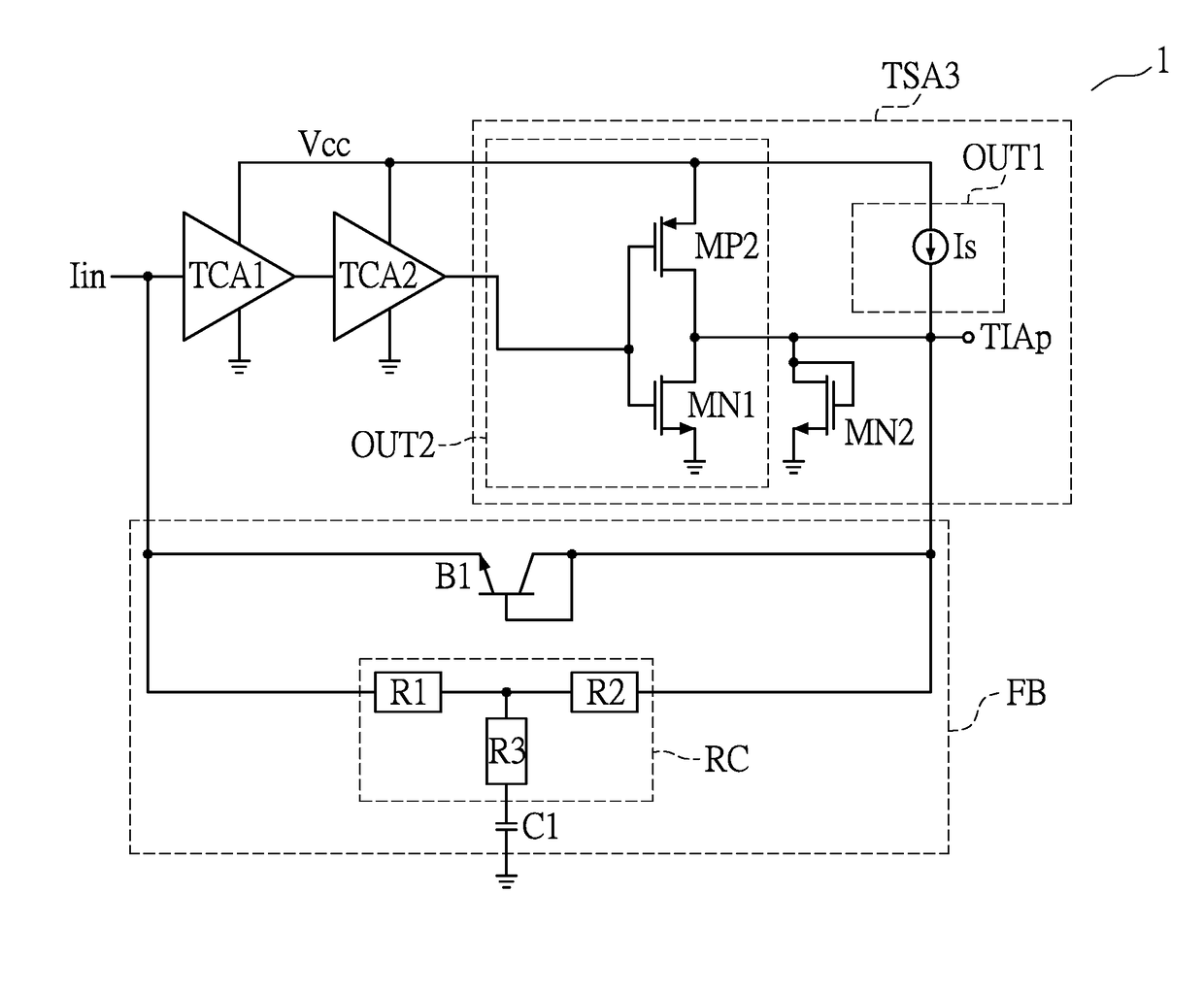
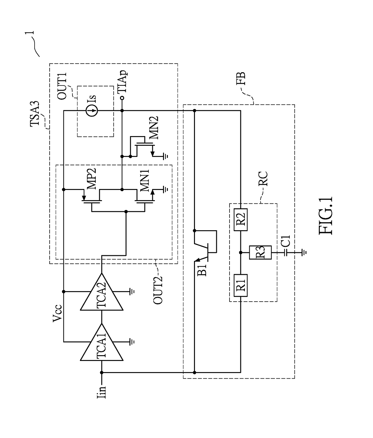
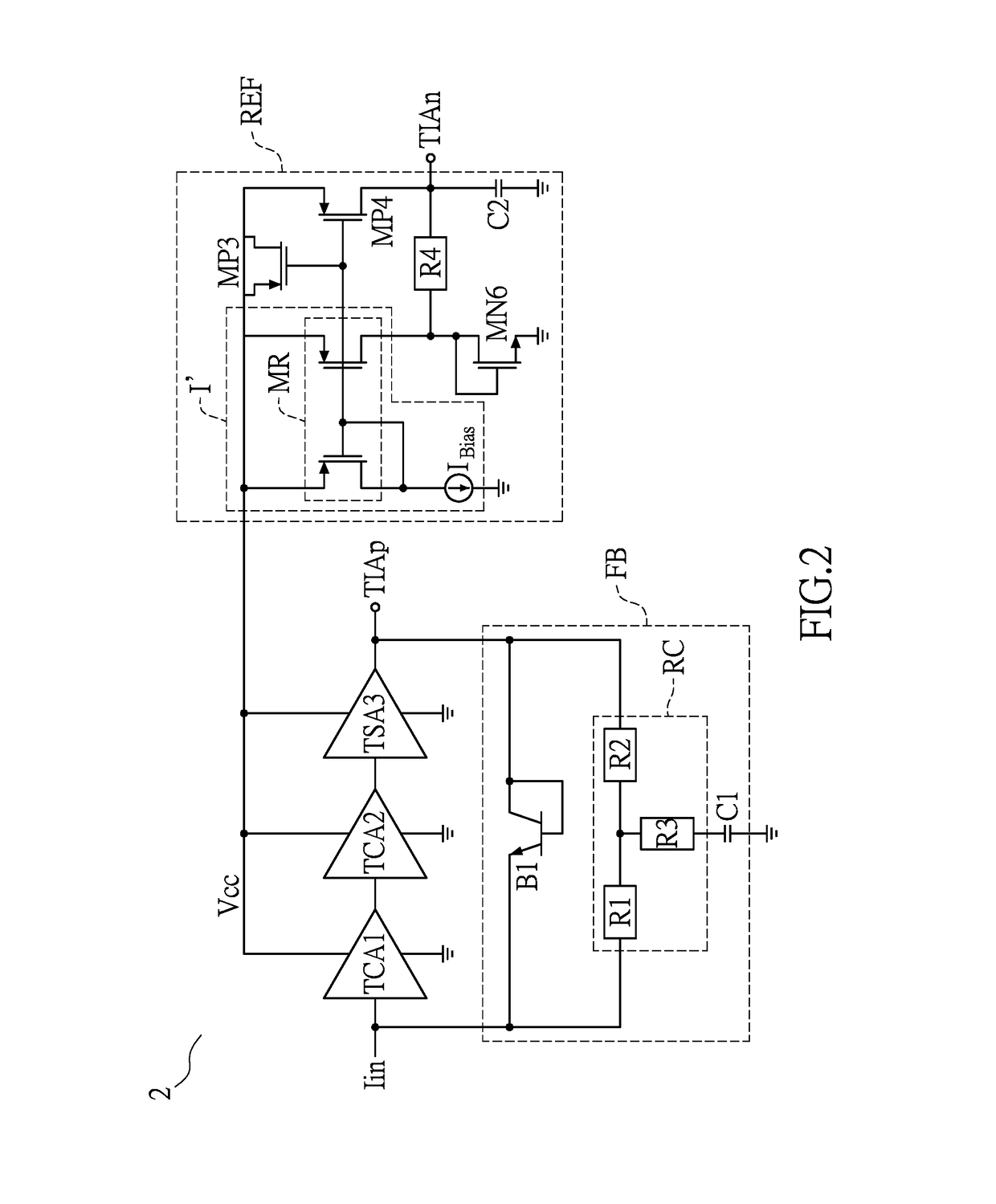
[0010]To sum up, in the trans-impedance amplifier provided in the embodiments of the present invention, the third-stage amplifier composed of the first output stage and the second output stage is arranged wherein the first output stage has a circuit design in a Class-A configuration and the second output stage has a circuit design in a Class-AB configuration, such that the amplifier has the advantages of both Class-A amplifier and Class-AB amplifier, thereby reducing propagation delay of the trans-impedance amplifier. On the other hand, in the reference voltage circuit of the trans-impedance amplifier provided in the embodiments of the present invention, the fifth transistor is arranged in parallel to the constant current unit and electrically connected between the supply voltage source and the output of the constant current unit, so as to improve on the instability of the reference voltage signal due to temperature changes or fabrication process variation.

Problems solved by technology

Single-stage TIA used in conventional optical receivers have a simple structure, but suffers from the problem that high sensitivity cannot be achieved due to insufficient transimpedance gain, because there is a close relation between the overall gain and bandwidth characteristics and the impedance of an output of the amplifier.
This difference between the maximum and the minimum of the input current causes increased propagation delay from high to low in the potential of an output of the TIA.

Method used


Image

  • Transimpedance amplifier
  • Transimpedance amplifier
  • Transimpedance amplifier

Examples


Embodiment Construction

[0017]Various exemplary embodiments will be described more fully with reference to the accompanying drawings, in which some exemplary embodiments are shown. However, the concept of the present invention may be embodied in many different forms and should not be construed as limited to the exemplary embodiments set forth herein. More specifically, the exemplary embodiments are provided so that this disclosure will be thorough and complete and will fully convey the scope of the invention to those skilled in the art. The size and relative sizes of layers and regions may be exaggerated for clarity in the drawings. Like numbers refer to like elements throughout.

[0018]It will be understood that although the terms first, second, third, and the like are used herein to describe various elements, these elements should not be limited by these terms. These terms are only used to distinguish one element from another element. Thus, a first element discussed below could be termed a second element w...


PUM


Abstract

Disclosed is a transimpedance amplifier, comprising a first-stage trans-conductance amplifier TCA, a second-stage TCA, a third-stage amplifier and a feedback circuit. The first-stage TCA is electrically connected to an input current source to receive a first input signal, and outputs a first output signal. The second-stage TCA is electrically connected to the first-stage TCA to receive the first output signal, and outputs a second output signal. The third-stage amplifier is electrically connected to the second-stage TCA to receive the second output signal, and outputs a third output signal. One end of the feedback circuit is electrically connected to the input of the first-stage TCA, and the other end of the feedback circuit is electrically connected to the output of the third-stage amplifier to stabilize the third output signal. The third-stage amplifier is composed of a first output stage and a second output stage.

Description

BACKGROUND OF THE INVENTION[0001]1. Field of the Invention[0002]The present invention relates to a trans-impedance amplifier (TIA), and in particular, to a trans-impedance amplifier for reducing propagation delay.[0003]2. Description of Related Art[0004]In optical communication systems, gain and sensitivity of optical receivers are important features, and both must be improved simultaneously in order to optimize transmission efficiency. Single-stage TIA used in conventional optical receivers have a simple structure, but suffers from the problem that high sensitivity cannot be achieved due to insufficient transimpedance gain, because there is a close relation between the overall gain and bandwidth characteristics and the impedance of an output of the amplifier.[0005]Therefore, generally, the architecture of multi-stage trans-conductance amplifier (TCA) is used to design optical receivers in order to achieve high transimpedance gain. Such an architecture of multi-stage TCA usually com...

Claims


Application Information

Patent Timeline
Patent Type & Authority Patents(United States)
IPC IPC(8): H03F1/30H03F3/08H03F3/04H03F1/34
CPCH03F3/04H03F1/34H03F2200/153H03F2200/408H03F2200/411H03F2200/555H03F1/14H03F3/3016
Inventor TAN, MENG-TONGLIM, HUEY-JENWANG, YOU-FA
Owner LITE ON SINGAPORE PTE LTD
Why Eureka
Try Eureka