Testing shield continuity of a cable or cabling installation using common mode insertion loss

a technology of shield continuity and common mode, which is applied in the direction of insulated conductors, cables, instruments, etc., can solve the problems of shield continuity verification techniques that are prone to yield false positive tests, direct current (dc) verification techniques that are prone to yield false negative tests, and the performance of crosstalk (xt) of cables, so as to increase the propagation delay and reduce the propagation delay

Active Publication Date: 2019-10-10
JOHN FLUKE MFG CO INC
View PDF2 Cites 2 Cited by
  • Summary
  • Abstract
  • Description
  • Claims
  • Application Information

AI Technical Summary

Benefits of technology

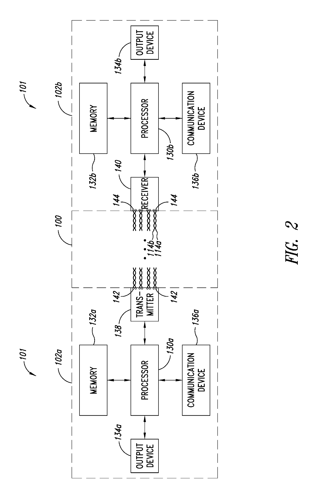
[0006]In an embodiment, the processor is configured to determine that the shield is continuous if the figure of merit is greater than or equal to the threshold and determine that the shield is discontinuous if the figure of merit is less than the threshold. In an embodiment, the processor is configured to determine whether the shield is continuous or discontinuous based on the common mode insertion loss in a subrange of the frequency range over which the first signal is transmitted. In an embodiment, the processor is configured to: identify the subrange based on a determined signal propagation delay of the cable or cabling installation.
[0007]In an embodiment, a location of the subrange in the frequency range is inversely correlated to the propagation delay such that an increase in the propagation delay results in shifting the subrange towards a beginning of the frequency range and a decrease in the propagation delay results in shifting the subrange towards an end of the frequency range. In an embodiment, the plurality of conductors of the cable or the cabling installation have a twisted pair arrangement in which a pair of conductors of the plurality of conductors are pair-wise twisted around each other. In an embodiment, a shield continuity testing device includes an output device, communicatively coupled to the processor, configured to receive the data representative of whether the shield is continuous or discontinuous, and output an indication of whether the shield is continuous or discontinuous.

Problems solved by technology

Discontinuities in the shield, which may manifest as a break or tear in the shield, degrade the crosstalk (XT) performance of the cable.
Direct current (DC) verification techniques of shield continuity are prone to yield a false positive test result (i.e., ‘pass’ a discontinuous shield) when the shield is grounded.
Further, the presence of a parasitic inductance, for example, due to shield termination at a connector, may cause shield verification techniques to yield a false negative test result (i.e., ‘fail’ a continuous shield).

Method used


Image

  • Testing shield continuity of a cable or cabling installation using common mode insertion loss
  • Testing shield continuity of a cable or cabling installation using common mode insertion loss
  • Testing shield continuity of a cable or cabling installation using common mode insertion loss

Examples


Embodiment Construction

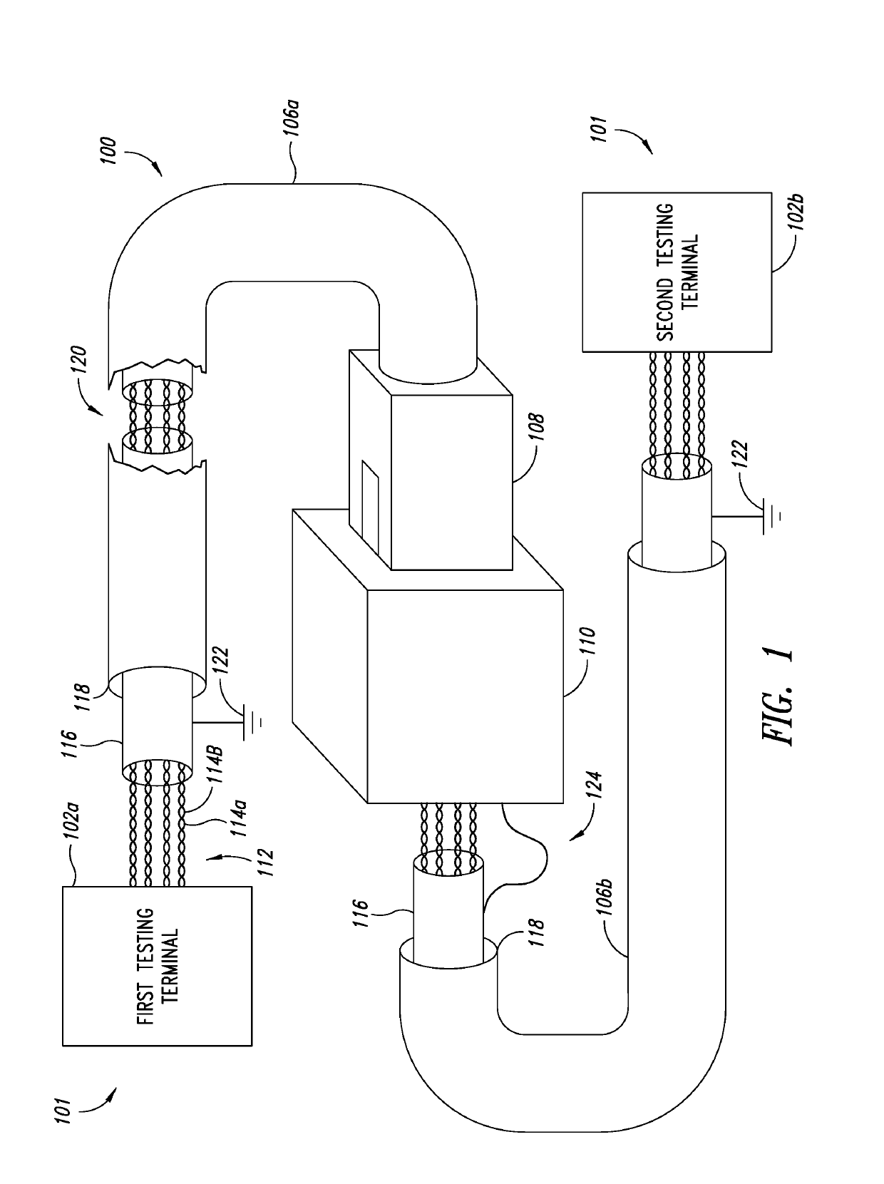
[0021]FIG. 1 shows a cabling installation 100 under test coupled to a testing device 101. The testing device includes a first testing terminal 102a and a second testing terminal 102b. The cabling installation 100 includes a first cable 106a and a second cable 106b (collectively referred to herein by the numeral alone) connected together using a connector plug 108 and a connector jack 110. It is noted that although a cabling installation 100 including multiple cables 106 is described with reference to FIG. 1, the techniques described herein may be used for testing an installation with any number of cables or for testing one cable.

[0022]Each cable 106 includes a plurality of twisted pairs of conductors 112. Each pair 112 includes a first conductor 114a and a second conductor 114b twisted around each other to reduce electromagnetic radiation and crosstalk and improve external electromagnetic interference rejection. Although the plurality of twisted pairs are shown in FIG. 1 to include ...


PUM

PropertyMeasurementUnit
frequencyaaaaaaaaaa
frequencyaaaaaaaaaa
frequencyaaaaaaaaaa

Abstract

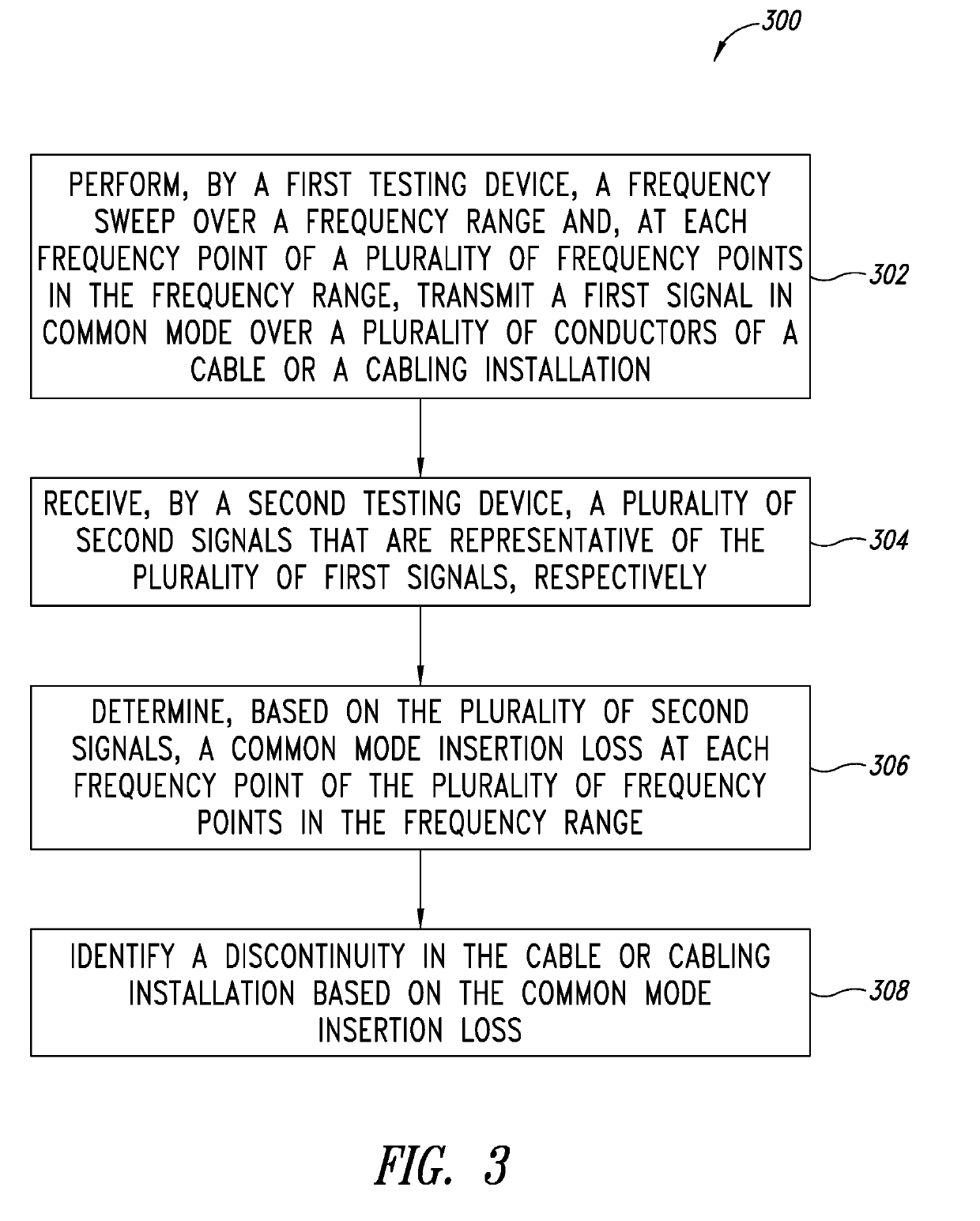
A method and apparatus for testing shield continuity are provided. In the method and apparatus, a transmitter transmits a first signal in common mode over a plurality of conductors of a cable or cabling installation having a shield. The first signal is transmitted in the common mode at a first end of the plurality of conductors. A receiver receives a plurality of second signals representative of the first signal at a second end of the plurality of conductors, respectively, and outputs data representative of the plurality of second signals. A processor receives the data representative of the plurality of second signals, determines a common mode insertion loss for the cable or cabling installation based on the plurality of second signals, determines, based on the common mode insertion loss, whether the shield is continuous or discontinuous and outputs data representative of whether the shield is continuous or discontinuous.

Description

BACKGROUNDTechnical Field[0001]This application is directed to a method and apparatus for detecting shield continuity in a cable or a cabling installation based on common mode insertion loss and, in particular, insertion loss of signals transmitted in common mode over one or more twisted pairs of conductors of the cable or cabling installation.Description of the Related Art[0002]Electrical cables include shields that reduce electromagnetic interference of an outside environment that can reach conductors of a cable. The cables may be twisted pairs of conductors. Discontinuities in the shield, which may manifest as a break or tear in the shield, degrade the crosstalk (XT) performance of the cable. Direct current (DC) verification techniques of shield continuity are prone to yield a false positive test result (i.e., ‘pass’ a discontinuous shield) when the shield is grounded. Further, the presence of a parasitic inductance, for example, due to shield termination at a connector, may caus...

Claims


Application Information

Patent Timeline
Patent Type & Authority Applications(United States)
IPC IPC(8): G01R29/08H01B7/32G01R31/02
CPCH01B11/06G01R29/0835G01R31/021H01B7/328G01R31/00G01R31/083G01R31/58G01R27/28G01R31/08G01R31/1272
Inventor BOTTMAN, JEFFREY S.
Owner JOHN FLUKE MFG CO INC
Why Eureka
Try Eureka