Method for providing an electrical connection and printed circuit board

a technology of printed circuit board and electrical connection, which is applied in the direction of fixed connection, inspection/indentification of circuit, and association of printed circuit non-printed electrical components, etc., can solve the problem of increasing the propagation delay of a signal path, reduce the propagation delay difference between the first cable and the second cable, and reduce costs

Active Publication Date: 2020-09-10
ADVANTEST CORP
View PDF0 Cites 0 Cited by
  • Summary
  • Abstract
  • Description
  • Claims
  • Application Information

AI Technical Summary

Benefits of technology

[0034]In an embodiment, a printed circuit board can comprise a first contact pad configured to contact a first cable, a second contact pad configured to contact a second cable, a third contact pad configured to contact a device, a fourth contact pad configured to contact a device, a first conductive structure configured to form a first conducting path connecting the first contact pad and the third contact pad, a second conductive structure configured to form a second conducting path connecting the second contact pad and the fourth contact pad. The first conductive structure and the second conductive structure can be configured to allow a modification of the propagation delay by definition of shapes of the first conducting path and the second conducting path. This means, for example, that the first conductive structure and/or the second conductive structure are at least at some parts widened, where conductive material can be removed in order to realize the first conducting path or the second conducting path with, for example, a special shape, which can define a modification of the propagation delay. With a different shaping of the first conducting path with regard to the second conducting path, the first conducting path can, for example, have a different length than the second conducting path. Thus, the ...

Problems solved by technology

With an elongation of the electrical length of the conduct...

Method used


Image

  • Method for providing an electrical connection and printed circuit board
  • Method for providing an electrical connection and printed circuit board
  • Method for providing an electrical connection and printed circuit board

Examples


Embodiment Construction

[0055]Equal or equivalent elements or elements with equal or equivalent functionality are denoted in the following description by equal or equivalent reference numerals even if occurring in different figures.

[0056]In the following description, a plurality of details is set forth to provide a more throughout explanation of embodiments of the present invention. However, it will be apparent to those skilled in the art that embodiments of the present invention may be practiced without these specific details. In other instances, well-known structures and devices are shown in block diagram form rather than in detail in order to avoid obscuring embodiments of the present invention. In addition, features of the different embodiments described herein after may be combined with each other, unless specifically noted otherwise.

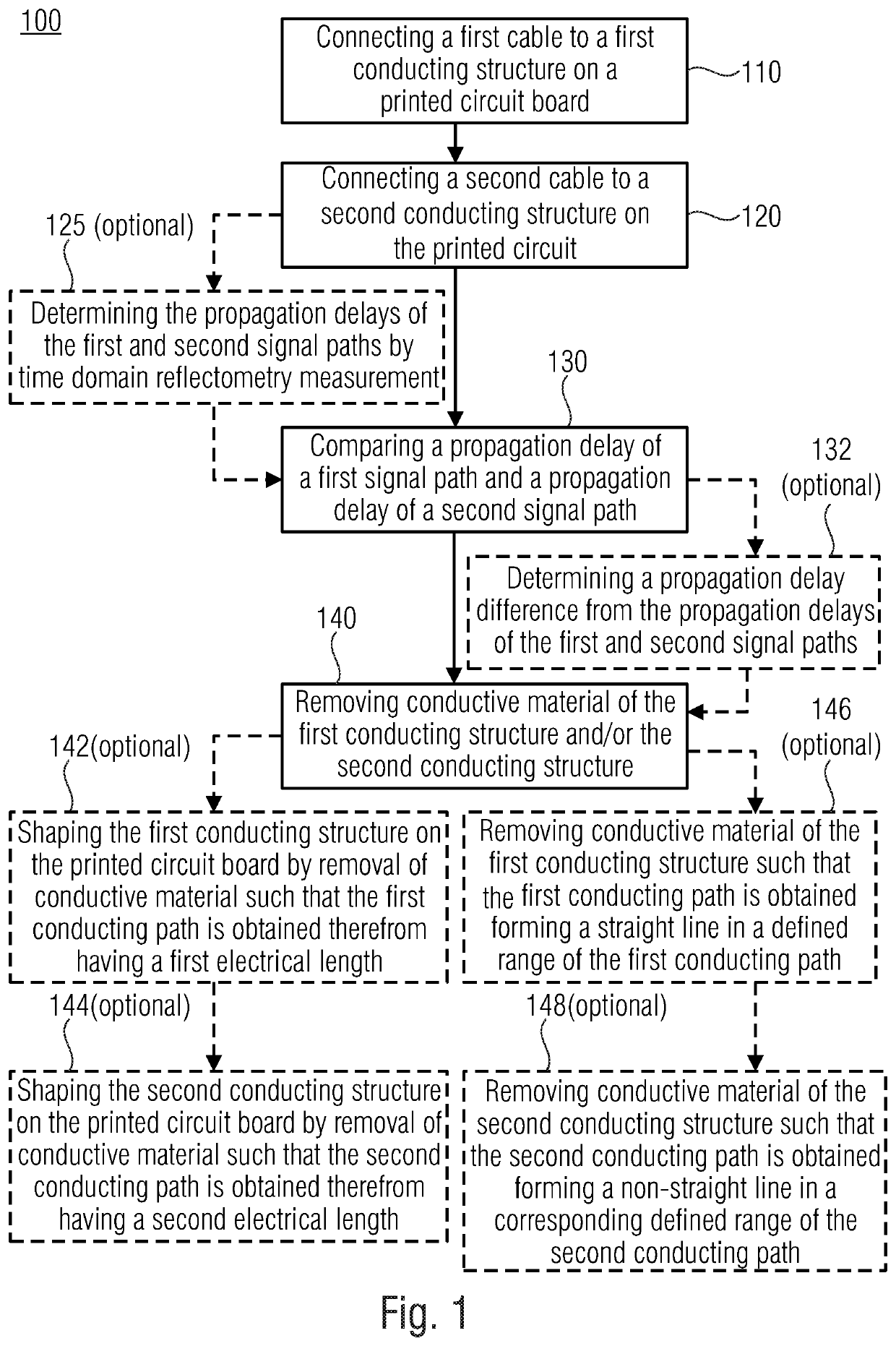
[0057]FIG. 1 shows a block diagram of a method 100 for providing an electrical connection. The method 100 comprises the step connecting 110 a first cable to a first condu...


PUM


Abstract

Method for providing an electrical connection, comprising connecting a first cable to a first conducting structure on a printed circuit board, connecting a second cable to a second conducting structure on the printed circuit board, comparing a propagation delay of a first signal path comprising the first cable and the first conducting structure on the printed circuit board, and a propagation delay of a second signal path comprising the second cable and the second conducting structure on the printed circuit board; and removing conductive material of the first conducting structure and/or of the second conducting structure, in order to modify an electrical length of the first conducting structure and/or of the second conducting structure, to obtain a first conducting path and a second conducting path, in dependence on a result of the comparison, in order to reduce a difference of the propagation delays between the first signal path and the second signal path.

Description

CROSS-REFERENCES TO RELATED APPLICATIONS[0001]This application is a continuation of co-pending International Application No. PCT / EP2019 / 055788, filed Mar. 7, 2019, which is incorporated herein by reference in its entirety.DESCRIPTIONTechnical Field[0002]Embodiments according to the invention related to a method for providing an electrical connection and a printed circuit board.Background of the Invention[0003]Today, cable assemblies with propagation time matching requirement better than + / −25 picoseconds are manufactured by measurement of each single wire, sorting and assembly related to the sorting result. This means large manual effort and therefore high cost.[0004]The cables are, for example, sorted into groups and for a differential cable pair two cables from one group have to be sorted, for example, to a line pair at a printed circuit board.[0005]In order to get a skew matching of better than + / −25 picoseconds for a line pair within a cable assembly, today it is necessary to pe...

Claims


Application Information

Patent Timeline
IPC IPC(8): H05K1/02H05K1/18H05K1/11G01R31/11
CPCH05K2201/10356H05K1/111H05K1/181H05K1/0213H05K1/0248H05K3/225H05K3/3421H05K1/0268H05K2201/09263H05K1/0245H05K1/117H01R12/53H05K1/0293H05K2203/173H05K2203/171H05K2203/175H05K2201/09209H05K2201/09236H05K2201/09281H05K2201/09736H05K2201/0979H05K1/02H05K1/11
Inventor EHRLER, SYLVIA
Owner ADVANTEST CORP
Why Eureka
Try Eureka