Convenient and automatic motor iron core production process

A production process and iron core technology, applied in the field of motor iron core production technology, can solve the problems of affecting the quality of slitting and shearing, low equipment utilization, low post-processing efficiency, etc., to improve equipment utilization and save labor. The effect of the process of handling and reducing manual transfer

Active Publication Date: 2021-03-30
JIANGYIN CHUANGJIA ELECTRICAL APPLIANCE
View PDF21 Cites 2 Cited by
  • Summary
  • Abstract
  • Description
  • Claims
  • Application Information

AI Technical Summary

Problems solved by technology

However, the previous production process needs to go through multiple processes, and manual collection and transfer between multiple processes are required, which is very inconvenient, and the previous production process also has the following defects:
[0003] 1. The production material of the iron core is silicon steel sheet, the raw material of silicon steel sheet is silicon steel strip, and the silicon steel strip is relatively curved when it is output from the leveling machine, which affects the quality of slitting and cutting
[0004] 2. The punch press can only punch the stator or the rotor alone, and the utilization rate of the equipment is not high
[0005] 3. The rotor needs post-processing after the riveting is completed. In the past, it was manually polished and deburred, so more labor is required, and the post-processing efficiency is not high.
[0006] 4. After the rotor and stator are processed, they need to be sent to the packaging area for packaging. However, in the past, the rotor and stator were carried by manual tools, which required labor and affected the processing efficiency.

Method used


Image

  • Convenient and automatic motor iron core production process
  • Convenient and automatic motor iron core production process
  • Convenient and automatic motor iron core production process

Examples


Embodiment Construction

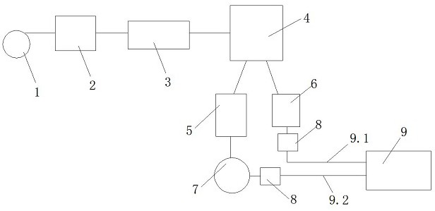
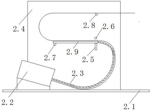
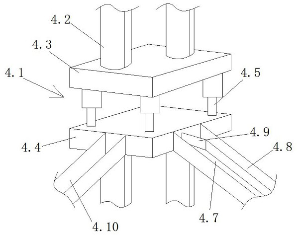
[0032] see Figure 1 to Figure 7 , the present invention relates to a convenient and automatic motor core production process. After the silicon steel strip is uncoiled from the unwinder 1, it is sent to the leveling machine 2 for leveling. After the silicon steel strip is output from the roller box 2.2, it is attached to the arc The lower end of the plate 2.3 is transported to the upper end of the arc-shaped plate 2.3 and passes between the support frame 2.5 and the bar 2.6, then transported to the support plate 2.9, then transported to the upper end of the transmission roller 2.8, and finally passes through the transmission Roller 2.8 makes the silicon steel strip at the output of the leveling machine smooth, and is transported to the slitting machine 3 to be cut into silicon steel sheets of required size, and then sent to the punching machine 4, and the stamping die 4.2 in the punching machine 4 simultaneously A stator or rotor is punched, and the silicon steel sheet is punche...


PUM


Abstract

The invention relates to a convenient and automatic motor iron core production process. The process is characterized in that a silicon steel strip is unwound at an unwinding machine and then is conveyed to a leveling machine to be leveled; the silicon steel strip at a discharge part of the leveling machine is leveled, and conveyed to a slitting machine to be slit into silicon steel sheets with required sizes; them the silicon steel sheets are conveyed into a punch press for punch forming; formed rotors are fed into a riveting pressing machine from a rotor channel, the multiple rotors are subjected to riveting pressing fixing after overlapping is completed, and the rotors are fed into a aftertreatment device after riveting pressing is completed, and clamped into a discharging channel afteraftertreatment is completed; formed stators are fed into a welding device from a stator channel, and fed into the discharging channel after welding is completed; the stators and rotors are grabbed through a gripper of a conveying mechanism, the stators are placed on a stator feeding channel, the rotors are placed on a rotor feeding channel, and finally the stators and the rotors are conveyed intoa packaging area, so that production of motor iron cores is completed. According to the convenient and automatic motor iron core production process, the production line is continuous, automatic feeding is achieved, the labor is saved, and the production efficiency is improved.

Description

technical field [0001] The invention relates to a convenient and automatic motor iron core production process. Background technique [0002] The iron core of the motor is mainly composed of the rotor and the stator. The main function of the stator is to generate a rotating magnetic field, and the main function of the rotor is to be cut by the magnetic force lines in the rotating magnetic field to generate output current. At present, the stator and rotor are generally made of silicon steel sheets, which can reduce the eddy current loss of the iron core. However, the previous production process needs to go through multiple processes, and manual collection and transfer between multiple processes are required, which is very inconvenient, and the previous production process also has the following defects: [0003] 1. The production material of the iron core is silicon steel sheet, the raw material of silicon steel sheet is silicon steel strip, and the silicon steel strip is rela...

Claims


Application Information

Patent Timeline
Patent Type & Authority Applications(China)
IPC IPC(8): B23P15/00H02K15/00
CPCB23P15/00H02K15/00
Inventor 徐浩
Owner JIANGYIN CHUANGJIA ELECTRICAL APPLIANCE
Why Eureka
Try Eureka