
Distributed optical fiber strain monitoring method based on crack propagation simulation

A distributed optical fiber and fracture expansion technology, which is applied in the directions of surveying, earthwork drilling, wellbore/well components, etc., can solve problems such as reducing the success rate of construction, unclear corresponding relationships, and difficult interpretation and analysis of measured data

Active Publication Date: 2021-03-30
CHINA UNIV OF PETROLEUM (EAST CHINA)
View PDF10 Cites 6 Cited by
  • Summary
  • Abstract
  • Description
  • Claims
  • Application Information

AI Technical Summary

Problems solved by technology

However, at present, the theoretical research of this technology is insufficient, and the corresponding relationship between formation strain and fracture propagation during the fracturing process is not clear, and there is no effective means to analyze the relationship between the optical fiber strain signal and the fracture propagation during the fracturing process, and it is difficult for engineers to carry out actual measurement. Interpretation and analysis of data reduces the success rate of construction

Method used


Image

  • Distributed optical fiber strain monitoring method based on crack propagation simulation
  • Distributed optical fiber strain monitoring method based on crack propagation simulation
  • Distributed optical fiber strain monitoring method based on crack propagation simulation

Examples


Embodiment Construction

[0085] The technical solutions in the embodiments of the present invention will be clearly and completely described below in conjunction with the accompanying drawings in the embodiments of the present invention. Obviously, the described embodiments are only part of the embodiments of the present invention, not all of them. Based on the embodiments of the present invention, all other embodiments obtained by persons of ordinary skill in the art without making creative efforts belong to the protection scope of the present invention.

[0086] It should be noted that if there is a directional indication (such as up, down, left, right, front, back...) in the embodiment of the present invention, the directional indication is only used to explain the position in a certain posture (as shown in the accompanying drawing). If the specific posture changes, the directional indication will also change accordingly.

[0087] In addition, if there are descriptions involving "first", "second" a...


PUM


Abstract

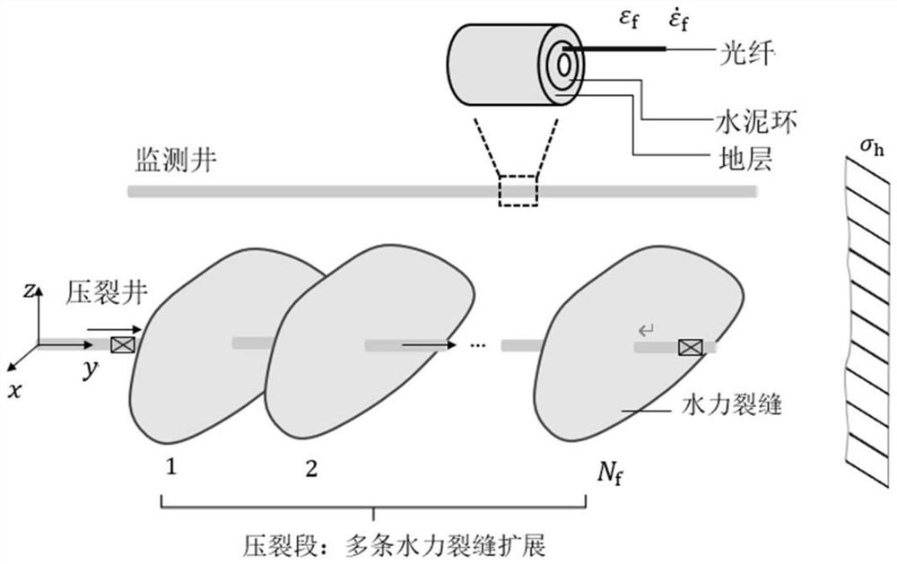
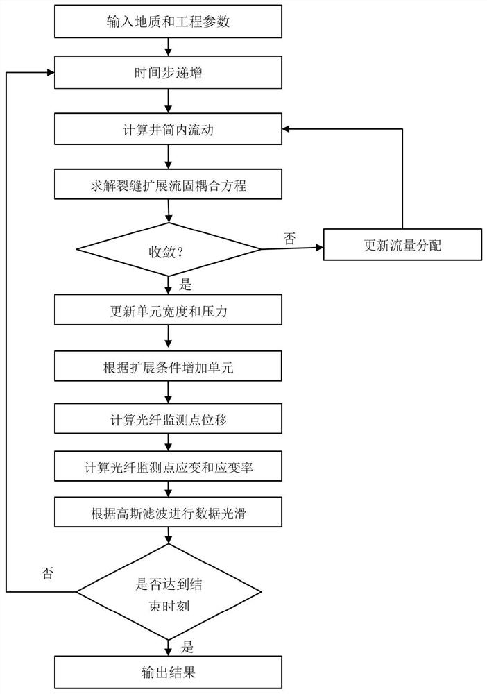
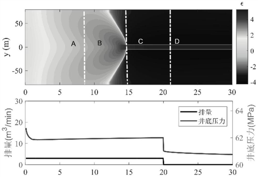
The embodiment of the invention relates to a distributed optical fiber strain monitoring method based on crack propagation simulation. The distributed optical fiber strain monitoring method comprisesthe following steps of S10, obtaining parameter information, and building a physical model of crack propagation and optical fiber strain monitoring, wherein the parameter information comprises wellbore and fracturing completion information, oil reservoir geological parameters, optical fiber positions and fracturing construction parameter information; S20, establishing a planar three-dimensional hydraulic fracturing crack propagation calculation model coupled with wellbore flow; S30, establishing an optical fiber strain and strain rate calculation model in the fracturing process; S40, smoothingdiscrete data, and drawing a cloud chart of optical fiber strain and fracturing well injection time and a cloud chart of optical fiber strain rate and fracturing well injection time; and S50, establishing a typical plate of optical fiber strain and strain rate signals and a model for judging that cracks collide with an optical fiber monitoring well, and fitting stratum parameters according to actual signals.

Description

technical field [0001] The embodiments of the present invention relate to the technical field of oil and gas field development, in particular to a distributed optical fiber strain monitoring method based on fracture propagation simulation. Background technique [0002] Horizontal well staged multi-cluster fracturing is the key technology for the development of unconventional oil and gas reservoirs at present. This technology generally uses the "clustered perforation" technology to realize a section of multi-fracture expansion, with high operating efficiency and low construction cost. It is the current low oil price background. The main well completion technology. In order to rationally optimize the construction design, the fracture propagation form is generally evaluated by microseismic monitoring during the fracturing process, but the generation mechanism of the microseismic signal does not completely correspond to the fracture rupture. [0003] Distributed optical fiber l...

Claims


Application Information

Patent Timeline
Patent Type & Authority Applications(China)
IPC IPC(8): E21B49/00E21B47/00E21B43/26
CPCE21B49/00E21B47/00E21B43/26
Inventor 陈铭郭天魁刘晓强齐宁徐建春罗明良刘德新王森吴飞鹏孙永鹏王文东
Owner CHINA UNIV OF PETROLEUM (EAST CHINA)
Learn More