
Eureka
For R&D, Eureka makes reading and utilizing patents & technical documents easy.
Eureka AIR
Designed for self-driven R&D workflows. Generate viable solutions, solve complex R&D challenges, empower your innovation with AI.

Eureka Materials
Designed for material experts only. Revolutionize your material R&D, from search, analyze, to developing new materials.

TechResearch
Generate reliable direction feasibility study reports for your R&D in just a few steps.

TechSeek
Discover and master advanced knowledge NOW. Basics, ideas, possibilities, all at once.

TechMind
As an expert in R&D Theories, TechMind can generates customized viable solutions instantly.

TechRisk
Analyze your overall solution with one click, know your potential R&D risks in advance.

TechMonitor
Get weekly tech updates, stay abreast of the latest tech innovations and key insights.
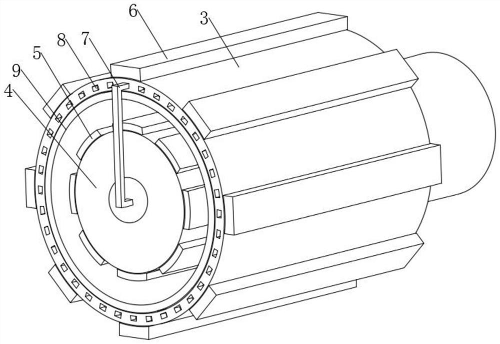
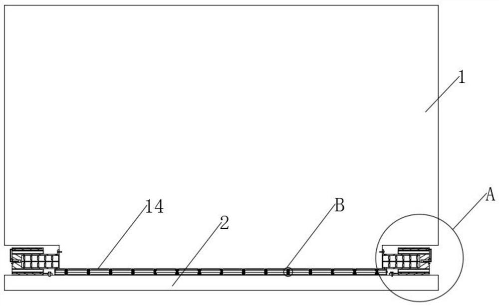
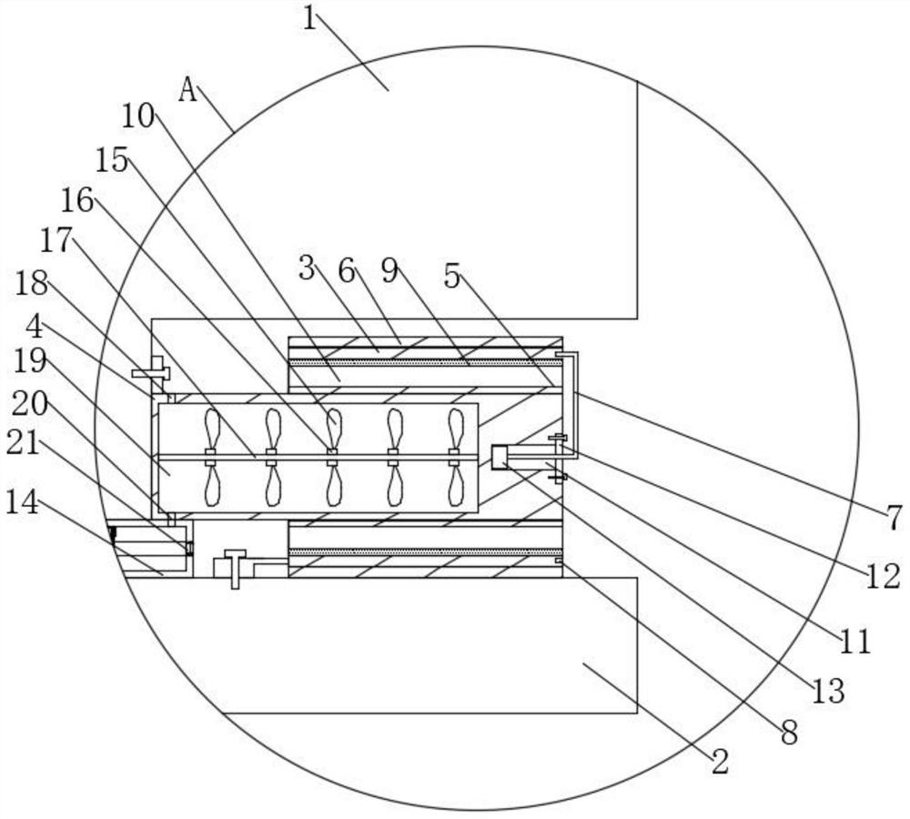
Stop fixing mechanism, and notebook computer rotating shaft based on stop fixing mechanism
A notebook computer, fixed mechanism technology, applied in the direction of electrical digital data processing, cleaning methods using gas flow, instruments, etc., can solve the problems of pad wear between shafts, poor yield, adhesive wear, etc., to avoid dust accumulation , Strong protection and practical effect
- Summary
- Abstract
- Description
- Claims
- Application Information
AI Technical Summary
Problems solved by technology
Method used
Image

Examples
Embodiment Construction
[0030] In order to make the object, technical solution and advantages of the present invention clearer, the present invention will be further described in detail below through the accompanying drawings and embodiments. However, it should be understood that the specific embodiments described here are only used to explain the present invention, and are not intended to limit the scope of the present invention.
[0031]It should be noted that when an element is said to be "disposed on, provided with" another element, it may be directly on the other element or there may also be an intermediate element. A component, it can be directly connected to another component or there may be an intermediate component at the same time. "Fixed connection" means fixed connection. There are many ways of fixed connection, which are not within the scope of protection of this article. The term used in this article "Vertical", "horizontal", "left", "right" and similar expressions are for the purpose o...
PUM
 Abstract
Description
Claims
Application Information
 - R&D Engineer
- R&D Manager
- IP Professional
- Industry Leading Data Capabilities
- Powerful AI technology
- Patent DNA Extraction
Browse by: Latest US Patents, China's latest patents, Technical Efficacy Thesaurus, Application Domain, Technology Topic, Popular Technical Reports.
© 2024 PatSnap. All rights reserved.Legal|Privacy policy|Modern Slavery Act Transparency Statement|Sitemap|About US| Contact US: help@patsnap.com