Denitrating coal economizer high-temperature bypass device

A technology of bypass device and economizer, applied in chemical instruments and methods, combustion product treatment, combustion methods, etc., can solve the problems of downstream air preheater clogging, reduced denitrification effect, corrosion, etc., to improve the use of Efficiency, denitrification efficiency inhibition, effect of improving denitrification efficiency

Inactive Publication Date: 2016-06-29
DATANG ENVIRONMENT IND GRP
View PDF9 Cites 9 Cited by
  • Summary
  • Abstract
  • Description
  • Claims
  • Application Information

AI Technical Summary

Problems solved by technology

[0002] In traditional flue gas denitrification, for the denitrification SCR device, the effective reaction temperature range is generally 300-420°C. When the boiler load is low, the flue gas temperature at the outlet of the low-temperature section of the economizer is low, and when the effective reaction temperature is lower than 300°C, it is the same as There is a certain deviation in the minimum allowable temperature of 300°C for denitrification, so the denitrification efficiency cannot be maintained. Under the condition of the reference oxygen content of 6%, the nitrogen oxide emission concentration is higher than 50 mg / m3, and it is easy to generate sulfate and escape (escaping) Ammonia reacts with sulfuric acid to produce ammonium bisulfate or ammonium sulfate. Ammonium bisulfate is in a viscous state at 150-230°C, which can easily cause ash, clogging and corrosion in the downstream air preheater and affect the stable operation of the entire system.
At the same time, after long-term use of the existing denitrification equipment, smoke and dust tend to accumulate on the filter layer, resulting in reduced denitrification effect

Method used


Image

  • Denitrating coal economizer high-temperature bypass device
  • Denitrating coal economizer high-temperature bypass device
  • Denitrating coal economizer high-temperature bypass device

Examples


Embodiment 1

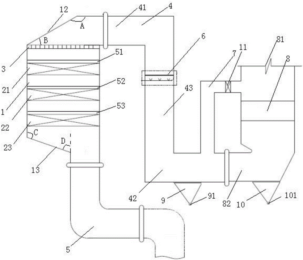
[0046] Example 1, such as figure 1 As shown, a high-temperature bypass device for a denitrification economizer described in an embodiment of the present invention includes an economizer 8 and an economizer bypass flue 7, and the inlet end of the economizer bypass flue 7 is connected to the economizer One side of the economizer 8 is connected, the entrance of the economizer bypass flue 7 is provided with an electric baffle door 11, the top of the economizer 8 is provided with an economizer inlet 81, and one side of the bottom of the economizer 8 is provided with an economizer Economizer outlet 82, economizer 8 bottom is provided with economizer outlet ash hopper 10, economizer outlet 82, outlet end of economizer bypass flue 7 and vertical flue 43 of desulfurization reactor inlet flue 4 connected, the vertical flue 43 is provided with an ammonia injection grid 6, the first horizontal flue 41 of the inlet flue 4 of the desulfurization reactor is connected with the top of the desu...

Embodiment 2

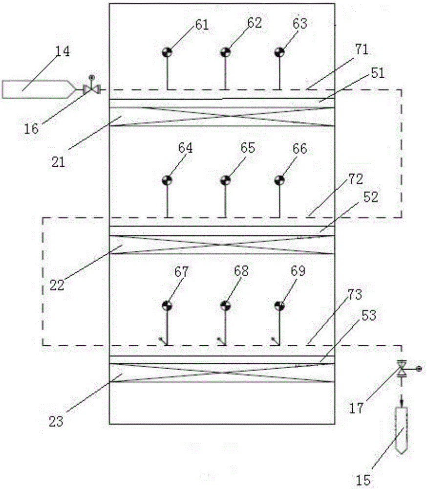
[0057] Such as figure 2 As shown, the difference from Example 1 is that it also includes a steam soot blowing device, which is arranged in the box of the denitration reactor, and the steam soot blowing device includes three steam soot blowing pipelines. The soot blowing steam inlet 14 of the boiler body is located outside one side of the box body in the denitration reactor. The first steam soot blowing pipeline 71 is located in the middle box of the denitrification reactor, the soot blowing steam inlet 14 of the boiler body is connected to the inlet end of the first steam soot blowing pipeline 71, and the first steam soot blowing pipeline 71 is located in the first screen Above the plate 51 , a first steam soot blower 61 , a second steam soot blower 62 and a third steam soot blower 63 are arranged on the first steam soot blowing pipeline 71 . The second steam soot blowing pipeline 72 is located in the box in the denitrification reactor, the inlet end of the second steam soot...

Embodiment 3

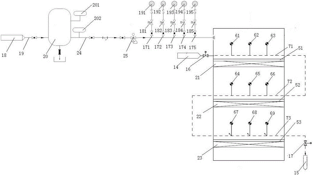
[0059] Such as image 3 As shown, the difference from Example 2 is that it also includes a sonic soot blowing device, and the sonic soot blowing device is arranged outside the box body 1 in the denitration reactor. The air inlet 18 is connected to an inlet end of an air inlet pipe 19 . The compressed air tank 20 is provided with an air inlet and an air outlet, the air inlet of the compressed air tank 20 is connected with the outlet end of the air intake pipe 19, the air outlet of the compressed air tank 20 is connected with the inlet end of the air supply pipe 24, and the air supply pipe 24 The outlet end of the outlet port is connected with the side wall of the box body in the denitrification reactor, the outlet end of the air supply pipe 24 is located above the first steam soot blowing pipeline 71, the compressed air tank 20 is provided with a first pressure gauge 201, and the air supply pipe 15 A second pressure gauge 202 is provided on the inlet end. The regulating valve...


PUM


Abstract

The invention discloses a denitrating coal economizer coal economizer high-temperature bypass device which comprises a coal economizer and a coal economizer bypass flue, wherein the inlet end of the coal economizer bypass flue is connected with one side of the coal economizer; an electrically operated baffle door is arranged at the inlet end of the coal economizer bypass flue; a coal economizer inlet is formed in the top of the coal economizer; a coal economizer outlet is formed in one side of the bottom of the coal economizer; a coal economizer ash hopper is arranged at the bottom of the coal economizer; the coal economizer outlet and the outlet end of the coal economizer bypass flue are connected with a vertical flue; an ammonia spraying grating is arranged on the vertical flue; a first horizontal flue is connected with the top of a denitrating reactor; a denitrating reactor inlet ash hopper is arranged at the bottom of a second horizontal flue; the bottom of the denitrating reactor is connected with a denitrating reactor outlet flue; and the denitrating reactor outlet flue is connected with an air preheater. The denitrating coal economizer coal economizer high-temperature bypass device provided by the invention has the beneficial effects that the necessary denitrating efficiency can be guaranteed, and the generation of sulfate and ammonium hydrogen sulfate can be inhibited; and large-grain ash slag in smoke can be removed, so as to avoid obvious hole blockage and erosion to a catalyst.

Description

technical field [0001] The invention relates to the technical field of out-of-stock technology, in particular to a high-temperature bypass device for a denitrification economizer. Background technique [0002] In traditional flue gas denitrification, for the denitrification SCR device, the effective reaction temperature range is generally 300-420°C. When the boiler load is low, the flue gas temperature at the outlet of the low-temperature section of the economizer is low, and when the effective reaction temperature is lower than 300°C, it is the same as There is a certain deviation in the minimum allowable temperature of 300°C for denitrification, so the denitrification efficiency cannot be maintained. Under the condition of the reference oxygen content of 6%, the nitrogen oxide emission concentration is higher than 50 mg / m3, and it is easy to generate sulfate and escape (escaping) Ammonia reacts with sulfuric acid to form ammonium bisulfate or ammonium sulfate. Ammonium bis...

Claims


Application Information

Patent Timeline
Patent Type & Authority Applications(China)
IPC IPC(8): F23J15/00F23J3/00B01D53/90B01D53/56
CPCF23J15/00B01D53/8631B01D53/90F23J3/00F23J2215/10F23J2215/20F23J2219/10
Inventor 刘玉新刘畅
Owner DATANG ENVIRONMENT IND GRP
Why Eureka
Try Eureka