Gas mixing method

A technology of gas mixing and gas mixer, which is applied in the direction of mixing method, gas and gas/steam mixing, mixer, etc., can solve problems such as stall instability, dust accumulation, flue wear, etc., and achieve the effect of reducing airflow resistance loss

Active Publication Date: 2016-06-22
ZHONGYE-CHANGTIAN INT ENG CO LTD
View PDF3 Cites 9 Cited by
  • Summary
  • Abstract
  • Description
  • Claims
  • Application Information

AI Technical Summary

Problems solved by technology

But the following problems exist in the existing flue gas mixer: due to the difference in pressure, temperature, flow, composition, etc. of the two strands of flue gas, the space of the flue and its elbow is limited (such as figure 2 ), during the mixing process of the two airflows, there are problems such as airflow refraction vortex, flue wear, dust accumulation, poor mixing effect, etc., and even airflow backdraft may occur, resulting in increased vibration of the flue gas circulation fan, stall instability and other working condition accidents

Method used


Image

  • Gas mixing method
  • Gas mixing method
  • Gas mixing method

Examples


Embodiment 1

[0044] Embodiment 1 A kind of gas mixer

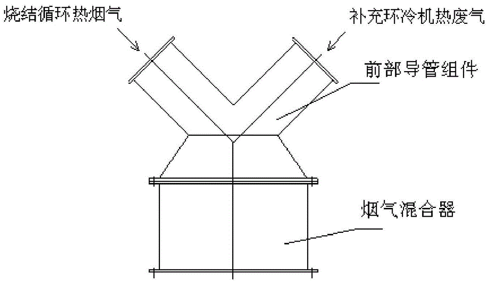
[0045] This embodiment provides a gas mixer, including a mixing cylinder 1, and a guide body 2 located in the mixing cylinder, coaxially arranged on the same bottom surface as the mixing cylinder; 6. At the lower end of the side wall of the mixing cylinder, two air inlet pipes 4 and 5 are arranged symmetrically with the center of the bottom surface of the mixing cylinder as a symmetrical point, and the air inlet directions of the two air inlet pipes are opposite.

[0046] The length Y of the mixing cylinder is in a certain proportion to the diameter X, and the optimum ratio is Y=(1.5~2)X; the mixing cylinder can be used vertically, horizontally, or tilted. The placement does not affect the mixing effect.

[0047] The diameters a and b of the inlet pipe are both determined by the total amount of gas and the flow rate, so as to ensure that the two airflows can rotate in the same direction after entering the mixing cylinder; correspondin...

Embodiment 2

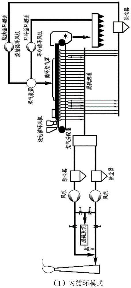
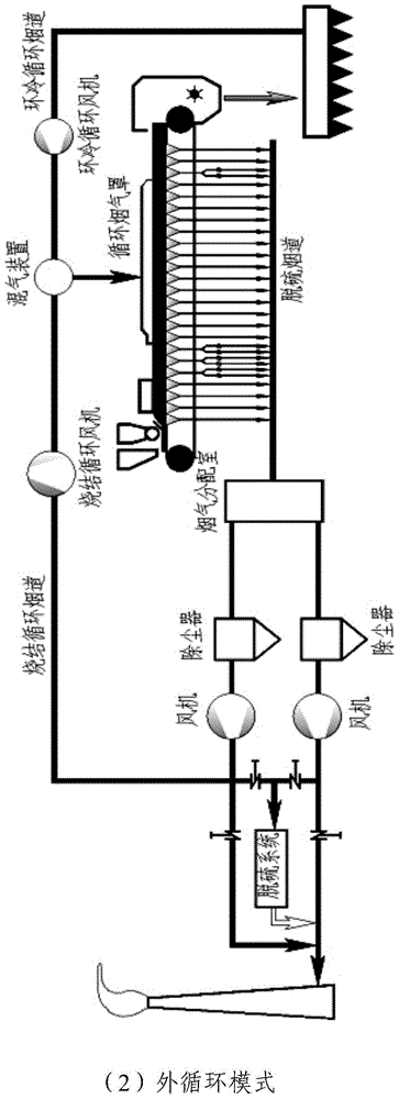
[0051] Embodiment 2 A method of gas mixing in a sintering flue gas circulation process

[0052] This embodiment provides a method for using the gas mixer described in the above embodiment 1 for gas mixing in the sintering flue gas circulation process, which specifically includes the following steps:

[0053] (1) Determine the size of the gas mixer:

[0054] According to the actual production requirements, the sintering circulation flue gas is 8000m 3 / min, the flow rate is 16.7m / s, and the hot exhaust gas of the ring cooling cycle is 8500m 3 / min, the flow rate is 16.7m / s; the mixed gas flow rate is 24m / s;

[0055] After calculation, the diameter of the intake pipe of the sintering cycle flue gas is a=3.2m, the diameter of the intake pipe of the hot exhaust gas of the ring cooling cycle is b=3.3m, the diameter of the bottom of the mixing cylinder of the entire flue gas mixer is X=8m, and the height Y=12m , the diameter of the bottom surface of the guide body Z=4m, the slope...


PUM


Abstract

The invention relates to a gas mixing method. According to the gas mixing method, two types of gas are sufficiently mixed by utilizing a gas mixer; a flow guide body with a specific ratio is arranged in a mixing cylinder of the gas mixer, and two gas inlet pipelines and one gas outlet pipeline are adapted, so that two paths of circulating gas can be sufficiently mixed, and furthermore, the effect of resistance loss of the two paths of gas flow is reduced. The gas mixing method provided by the invention can be suitable for a mixing process of various types of flue gas in an industrial production field, and is particularly suitable for mixing sintering circulating flue gas and ring cooling circulating hot waste gas, and mixing the sintering circulating flue gas and air in a sintering flue gas circulating process.

Description

technical field [0001] The invention relates to a gas mixing method, in particular to a gas mixing method in a sintering flue gas circulation process, and belongs to the technical field of gas mixing. Background technique [0002] The sintering flue gas circulation process means that a part of the hot flue gas generated during the sintering production process is not discharged into the atmosphere, but returned to the sintered material surface for reuse after simple treatment. The sintering flue gas circulation process flow is shown in figure 1 . Such as figure 1 As shown, the sintering flue gas circulation process mainly includes the following facilities: sintering circulation fan, ring cooling circulation fan, multi-pipe dust collector, flue gas mixer, flue gas distributor, circulating flue gas hood and pipelines between connected equipment system etc. But the following problems exist in the existing flue gas mixer: due to the difference in pressure, temperature, flow, ...

Claims


Application Information

Patent Timeline
Patent Type & Authority Applications(China)
IPC IPC(8): B01F3/02B01F5/00B01F5/06B01F23/10
CPCB01F23/10B01F25/10B01F25/423
Inventor 景涛周志安李文林李继淦夏春才
Owner ZHONGYE-CHANGTIAN INT ENG CO LTD
Why Eureka
Try Eureka