Power divider, adjusting method and power distribution method

An adjustment method and power divider technology, which are applied to waveguide-type devices, circuits, connecting devices, etc., can solve the problems of long signal line length and large power divider area of ​​the power divider, so as to reduce the overall area and reduce the loss. Effect

Pending Publication Date: 2021-03-30
SANECHIPS TECH CO LTD
View PDF4 Cites 1 Cited by
  • Summary
  • Abstract
  • Description
  • Claims
  • Application Information

AI Technical Summary

Problems solved by technology

[0007] Embodiments of the present invention provide a power divider, an adjustment method, and a power distribution method to at least solve the problem in the related art that the length of the signal line of the power divider is relatively long and the area of ​​the power divider is relatively large

Method used


Image

  • Power divider, adjusting method and power distribution method
  • Power divider, adjusting method and power distribution method
  • Power divider, adjusting method and power distribution method

Examples


Embodiment 1

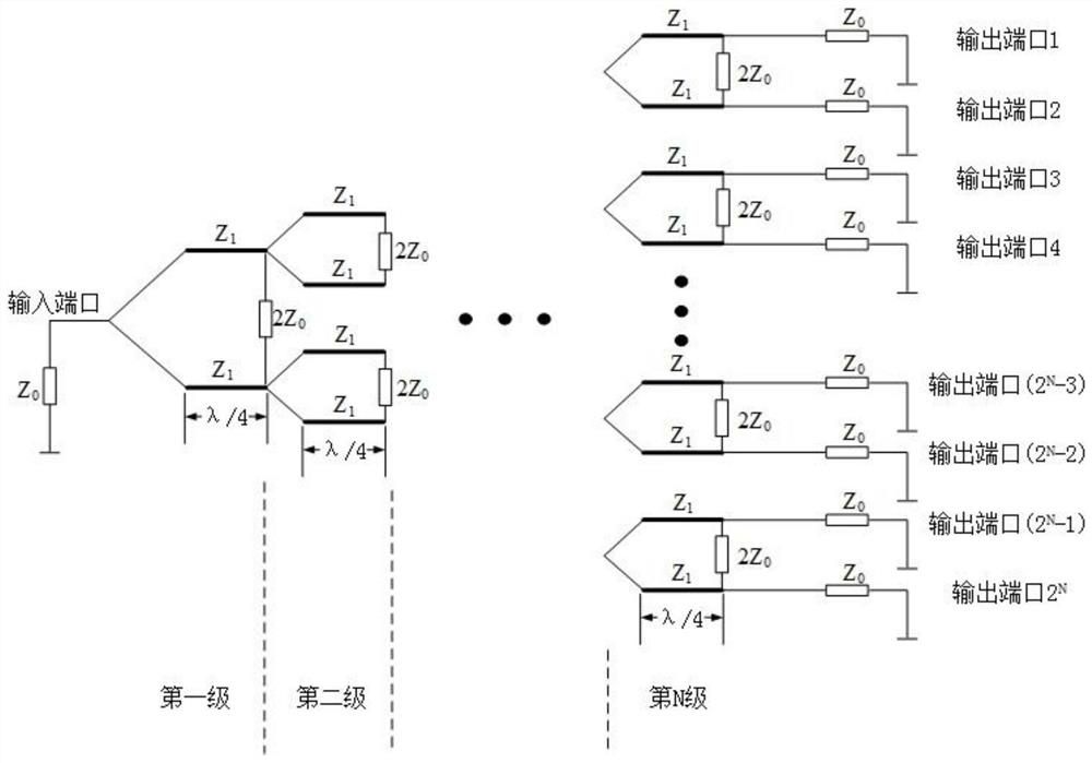
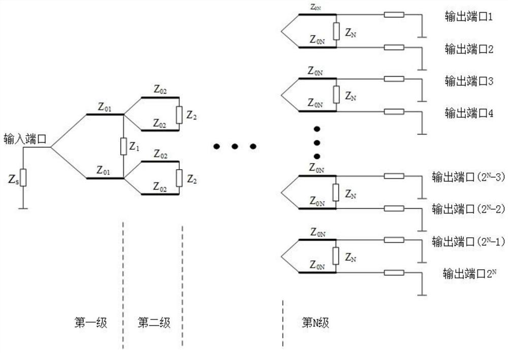
[0044] An embodiment of the present invention provides a power splitter, image 3 is a structural block diagram of a power splitter according to an embodiment of the present invention, such as image 3 shown, including:

[0045] N power division units, wherein, N power division units are cascaded to form an M-level cascade structure, each power division unit includes an input port and two output ports, and the Kth level power division unit in the cascade structure Satisfy the following relationship:

[0046] The input impedance of the Kth class power division unit is conjugate matched with the output impedance of the unit connected to the input end of the Kth class power division unit, and the output impedance of the Kth class power division unit is matched with the load of the Kth class power division unit Impedance conjugate matching, wherein N, K and M are all positive integers greater than or equal to 1.

[0047] Through the embodiment of the present invention, since th...

Embodiment approach

[0071] The technical problem to be solved by the embodiments of the present invention is: In order to overcome the problems of excessive area and large transmission loss existing in the prior art, the embodiments of the present invention provide a design method of a new miniaturized power splitter, Through this design method, a power divider whose area is reduced to at least one-third of the original and transmission loss is also reduced can be obtained.

[0072] Figure 5 is a schematic diagram of the implementation process of a miniaturized power divider according to an optional embodiment of the present invention, such as Figure 5As shown, the method for miniaturizing the power splitter described in the embodiment of the present invention includes the following steps:

[0073] The first step: first clearly require a point 2 N The source impedance Z of the power divider S and load impedance Z L , such as setting the target source impedance and target load impedance of t...


PUM


Abstract

The invention provides a power divider, an adjusting method and a power distribution method. The power divider comprises N power dividing units, the N power dividing units are cascaded to form an M-stage cascade structure, and each power dividing unit comprises an input port and two output ports. A K-th-stage power dividing unit in the cascade structure meets the following relation that the inputimpedance of the K-th-stage power dividing unit is in conjugate match with the output impedance of a unit connected with the input end of the K-th-stage power dividing unit, the output impedance of the K-th-stage power dividing unit is in conjugate match with the load impedance of the K-th-stage power dividing unit, and N, K and M are all positive integers greater than or equal to 1. According tothe invention, the problem that the area of the power divider is large due to the fact that the length of a signal line of the power divider is large in the prior art is solved, the overall area of the power divider is reduced, and the loss of the power divider is reduced.

Description

technical field [0001] The present invention relates to the communication field, in particular to a power divider, an adjustment method and a power distribution method. Background technique [0002] In recent years, mobile communications, electronic countermeasures, and satellite communications are developing toward miniaturization, broadband, and higher operating frequency bands, and the requirements for frequency and bandwidth are also developing toward high-frequency broadband. In the era of rapid development of 5G technology, the millimeter wave frequency band has attracted extensive research due to its characteristics of large bandwidth and high capacity. Since the high-frequency signal will have a large loss during transmission, which will affect the communication quality, it is necessary to apply multi-channel phased array technology, and the power divider (power divider) is an essential part of it. With the demand for integrated miniaturization of radio frequency de...

Claims


Application Information

Patent Timeline
IPC IPC(8): H01P5/16
CPCH01P5/16H01P5/19H01P5/12
Inventor 黄蓓
Owner SANECHIPS TECH CO LTD
Why Eureka
Try Eureka