
Remote maintenance method and remote maintenance device for defibrillator

A remote maintenance and defibrillator technology, applied to instruments, alarms that rely on opening, electrical components, etc., can solve problems such as rising maintenance costs, impossible tracking at all times, high power consumption, etc., achieve efficient wireless communication, and realize energy saving The effect of simple electrical design and communication coding

Active Publication Date: 2021-03-30
BEIJING M&B ELECTRONIC INSTR CO LTD
View PDF9 Cites 2 Cited by
  • Summary
  • Abstract
  • Description
  • Claims
  • Application Information

AI Technical Summary

Problems solved by technology

The disadvantage of this maintenance method is that the timeliness is poor and it is impossible to track it all the time. The second is that as the number of installations increases, the maintenance cost increases year-on-year, and the cost is too high
However, in order to set up a monitoring device that can automatically collect defibrillator self-test data, it is necessary to additionally set up a box for placing the monitoring device next to the defibrillator, and set a pluggable device between the defibrillator and the data acquisition device. Cables are used to achieve wired communication connections, or wireless communication is used to maintain long-term communication or regular regular communication, which not only complicates the overall structure, but also consumes relatively large power. Usually, it is necessary to set up power supply lines to lead the mains to On-site, power the relevant devices through the power adapter

Method used


Image

  • Remote maintenance method and remote maintenance device for defibrillator
  • Remote maintenance method and remote maintenance device for defibrillator
  • Remote maintenance method and remote maintenance device for defibrillator

Examples


Embodiment Construction

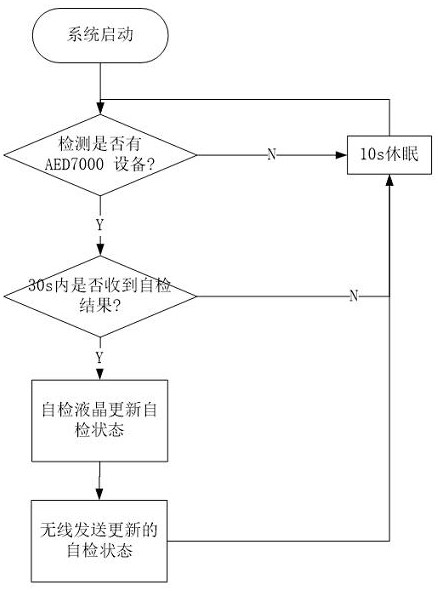
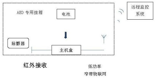
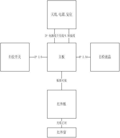
[0056] see Figure 1-12 This kind of monitoring device is usually arranged in public places with many people, such as subway stations, shopping malls, etc. Usually, the hanging box 10 can be hung on the wall, and the front of the hanging box is provided with a box door 11. A monitoring host box 30 is arranged in the box, and the monitoring host box is fixed on the bottom of the box, and is in a hollow groove-shaped structure. The opening of the defibrillator slot faces upwards, and the defibrillator 50 is inserted On the defibrillator 34 on the monitoring host box, the monitoring host box is the casing of the monitoring host, and its inner cavity can be used to accommodate and install corresponding monitoring host circuits (including devices, components, etc.), and these circuits can basically be Installed in the monitoring host box, the specific layout can be based on actual needs.

[0057] The defibrillator slot is adapted to the shape of the lower part of the defibrillator...


PUM


Abstract

The invention relates to a remote maintenance method and a remote maintenance device for a defibrillator. The method comprises the steps: a monitoring host communicates with a defibrillator in a timing intermittent awakening mode in a timing mode to obtain self-checking information of the defibrillator, the communication mode of the monitoring host and the defibrillator is infrared communication,and after the self-checking information of the defibrillator is collected, a low-power-consumption self-checking liquid crystal display is driven to display equipment state information of the defibrillator; and self-checking information of the defibrillator is sent through the NBIoT low-power narrow-band Internet-of-Things wireless module, and the defibrillator enters a dormant state in a port line change interruption mode when no AED exists. The monitoring host and the defibrillator are arranged in a hanging box of the device, a monitoring host box is of a hollow groove-shaped structure and is provided with a defibrillator inserting groove used for inserting the defibrillator, and an infrared window capable of allowing infrared rays to penetrate through is formed in the defibrillator inserting groove. The infrared window is located at a position opposite to the infrared communication window on the defibrillator which is inserted in place. The device is small in size, convenient to setand low in power consumption.

Description

technical field [0001] The invention relates to a remote maintenance device for a defibrillator, in particular to a remote monitoring device for a defibrillator for maintaining the defibrillator. Background technique [0002] Automated External Defibrillator (Automated External Defibrillator, referred to as defibrillator or AED) can be placed in public places to treat people with sudden cardiac arrest, which is sudden cardiac death Can cause a person to suddenly lose consciousness, become unresponsive, and not breathing. After sudden cardiac death, if a defibrillator can be used for timely treatment within 3-5 minutes, the lives of most people will be saved without sequelae, which in turn will help reduce the loss of the country and society. [0003] 544,000 people die of cardiac arrest every year, and more than 95% of them occur in public places outside the hospital. Therefore, the more defibrillators are installed in public places, and they are always in good condition an...

Claims


Application Information

Patent Timeline
Patent Type & Authority Applications(China)
IPC IPC(8): H04L29/08G16Y40/10G08B13/08
CPCH04L67/12G16Y40/10G08B13/08Y02D30/70
Inventor 吴豪杰马琴张润令杨志浩
Owner BEIJING M&B ELECTRONIC INSTR CO LTD
Learn More