
Safety device and method for coil loading and unloading process

A safety device, the top-level technology, is applied in the field of safety devices in the process of loading and unloading, which can solve the problems of potential safety hazards and inconvenient operation of the trolley, and achieve the effect of ensuring safety protection and convenient maintenance.

Inactive Publication Date: 2021-04-02
CHINA NAT HEAVY MACHINERY RES INSTCO
View PDF6 Cites 1 Cited by
  • Summary
  • Abstract
  • Description
  • Claims
  • Application Information

AI Technical Summary

Problems solved by technology

[0003] In order to overcome the problems of inconvenient operation of the trolley and potential safety hazards, the present invention provides a safety device and method for the process of loading and unloading rolls. The present invention is simple in structure, strong in practicability, and easy to implement

Method used


Image

  • Safety device and method for coil loading and unloading process
  • Safety device and method for coil loading and unloading process

Examples


Embodiment 1

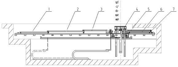
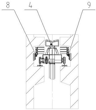
[0021] In order to overcome the problems of inconvenient operation of the trolley and potential safety hazards, the present invention provides such Figure 1-2 Shown is a safety device and method for the process of loading and unloading rolls. The present invention is simple in structure, strong in practicability, and easy to implement.

[0022] A safety device for the process of loading and unloading coils, comprising a left track surface assembly 8 and a right track surface assembly 9, a trolley 4, a rear side plank and a front side plank, the left track surface assembly 8 and the right track surface The assembly 9 is arranged symmetrically with respect to the trolley 4, and is respectively installed on the foundation walls on both sides of the trolley 4; All are multi-layer, and the bottom rear deck and the bottom front deck are rolled on the left track surface assembly 8 and the right track surface assembly 9 by rollers; the uppermost rear deck and the uppermost front deck...

Embodiment 2

[0025] Based on the basis of Example 1, in this embodiment, preferably, both ends of the upper surface of the rear side plank of the lowermost layer and the rear side plank of the middle layer are provided with limit baffles; Limiting baffles are also provided at both ends of the upper surface of the front side plank of the middle layer.

[0026] In the present invention, both the rear deck and the front deck can be made of Q235 steel to save costs and ensure that people can stand on the deck without bending the deck.

[0027] Preferably, anti-collision blocks are provided at each of the limit baffles.

[0028] Preferably, the anti-collision block is rubber.

[0029] In the present invention, the rubber anti-collision block is selected to ensure that each plank will not cause damage to the plank itself when it is in the limit position, and the service life of the present invention is improved. The anti-collision block can be made of various materials that can buffer force, n...

Embodiment 3

[0036] Based on the basis of Example 1, in this embodiment, preferably, the front side decking is three layers, including the front side upper decking board 5, the front side middle decking board 6 and the front side lower decking board 7; The lengths of the upper plank 5 and the front lower plank 7 are all less than the length of the front middle plank 6 .

[0037] Preferably, the rear decking is three layers, including the rear lower decking 1, the rear middle decking 2 and the rear upper decking 3, the rear lower decking 1, the rear middle decking 2 and the rear upper deck The planks 3 have the same length.

[0038] Such as figure 1 with figure 2 As shown, the front side lower floor plank 7 and the rear side lower floor plank 1 run on the left track surface assembly 8 and the right track surface assembly 9 by rollers; the front side middle floor plank 6 runs on the front side lower floor plank 7 and passes through the front The position is locked by the mechanical limit...


PUM


Abstract

The invention provides a safety device and method for the coil loading and unloading processes. The device comprises a left side track surface assembly, a right side track surface assembly, a trolley,rear side laying plates and front side laying plates, the left side track surface assembly and the right side track surface assembly are symmetrically arranged relative to the trolley and are arranged on foundation walls on the two sides of the trolley correspondingly, the rear side laying plates and the front side laying plates are arranged on the front side and the rear side of the trolley correspondingly, the multiple layers of rear side laying plates and the multiple layers of front side laying plates are arranged, the rear side laying plate at the lowermost layer and the front side laying plate at the lowermost layer roll on the left side track surface assembly and the right side track surface assembly through rolling wheels correspondingly, the rear side laying plate at the topmostlayer and the front side laying plate at the topmost layer are connected to the upper part of a transverse moving mechanism of the trolley, the rear side laying plate of the upper layer moves on the upper surface of the rear side laying plate of the lower layer close to the rear side laying plate of the upper layer through rolling wheels, and the rolling wheels are arranged on the lower side surfaces of the ends, close to the corresponding front side laying plate of the upper layer and the corresponding rear side laying plate of the upper layer, of the front side laying plate of the middle layer and the rear side laying plate of the middle layer. The device and the method have the advantages of being simple in structure, high in practicability and easy to implement.

Description

technical field [0001] The invention relates to the technical field of metallurgical equipment, in particular to a safety device and method for loading and unloading coils. Background technique [0002] In the field of metallurgical equipment, especially metal strip processing units, the process of trolley loading, unloading, tail coiling, loading and unloading sleeves, etc., such as: the trolley takes coils from the saddle and rolls to the uncoiler or takes the sleeve and puts the sleeve to the Coiler, the trolley takes the finished roll from the coiler to the saddle for packaging, and the trolley unloads the tail coil from the uncoiler or unloads the sleeve to the saddle. In the above process, especially unwinding of strapping before winding, packaging of finished products, inspection and maintenance of trolley motors, etc., operators need to intervene. The trolley tunnel is deep, and falling into the tunnel seriously threatens the life safety of the operator, and there a...

Claims


Application Information

Patent Timeline
IPC IPC(8): B21C47/24
CPCB21C47/24
Inventor 高聪敏刘忠宝张康武孙亚波李剑
Owner CHINA NAT HEAVY MACHINERY RES INSTCO
Learn More