A desk feet assembly machine
A technology for assembly machines and desks, applied in assembly machines, metal processing equipment, metal processing, etc., can solve problems such as wear, low work efficiency, and unstable components, so as to reduce labor intensity, improve work efficiency, and reduce costs. The effect of time
- Summary
- Abstract
- Description
- Claims
- Application Information
AI Technical Summary
Problems solved by technology
Method used
Image

Examples
Embodiment 1
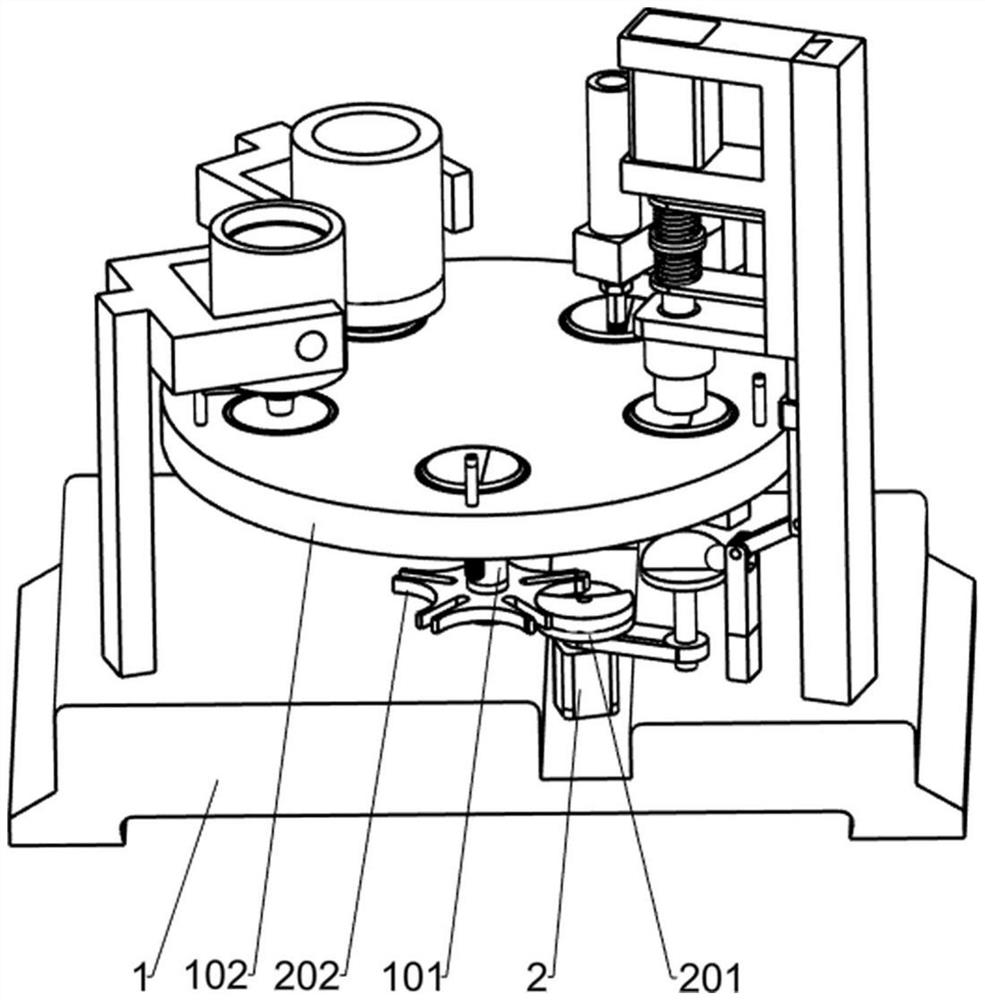
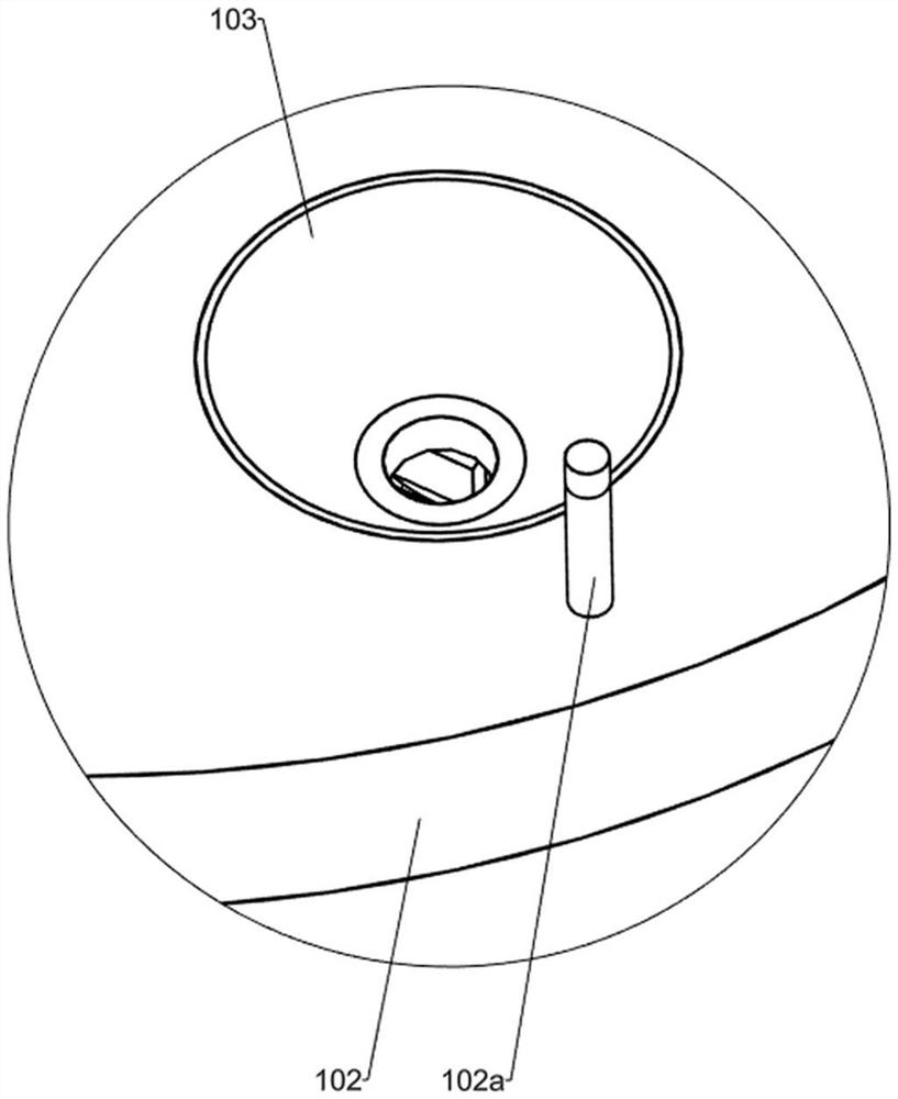
[0038] A desk foot assembly machine, such as Figure 1-2 and Figure 11-13 As shown, it includes a base 1, a support shaft 101, a workbench 102, a retaining column 102a, a power mechanism, a reciprocating mechanism and a mounting mechanism. The upper end of the workbench 102 is provided with five stations, each station of the workbench 102 is provided with a retaining post 102a, the power mechanism is fixedly installed on the top of the base 1, and the power mechanism is located on the right front side of the support shaft 101. The mechanism is fixedly connected with the support shaft 101, the reciprocating mechanism is fixedly installed on the right side of the base 1, the reciprocating mechanism is connected with the power mechanism, the installation mechanism is fixedly connected with the reciprocating mechanism, and the installation mechanism is located above the right station of the workbench 102.
[0039] Working steps: Before assembling the parts, the worker puts the p...
Embodiment 2
[0041] On the basis of Example 1, such as figure 1 As shown, the power mechanism includes a first motor 2, a dial 201 and an intermittent disc 202, the first motor 2 is fixedly installed in the middle of the base 1, the first motor 2 is located on the right side of the support shaft 101, and the dial 201 is fixedly installed On the output shaft of the motor, the intermittent disk 202 is fixedly installed in the middle of the support shaft 101, the small raised part of the dial 201 is slidingly connected with the convex slider 608a of the intermittent disk 202, and the large raised part of the dial 201 is connected with the intermittent The arcuate portion of the disc 202 is slidably connected.
[0042] Working steps: When preparing to assemble parts, start the motor, the output shaft of the motor starts to rotate, and the dial 201 fixed on the output shaft of the motor rotates accordingly, and the small protrusions on the dial 201 are in the grooves opened on the intermittent ...
Embodiment 3
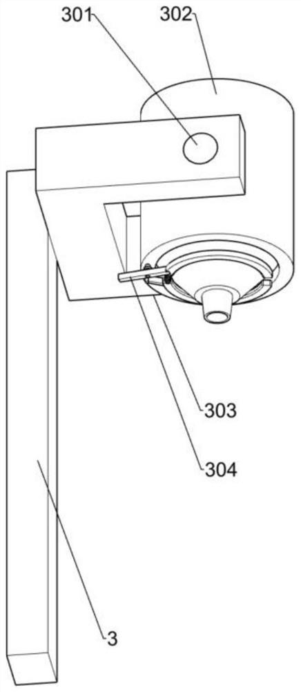
[0048] On the basis of Example 2, such as Figure 3-4As shown, a first feeding mechanism is also included, and the first feeding mechanism includes a first support 3, a first connecting column 301, a first bucket 302, a second connecting column 303, a first connecting rod 304, a first The sector gear 305, the second connecting rod 306, the second sector gear 3061, the clamp rod 307 and the first tension spring 308, the two first brackets 3 are fixedly installed on the left and rear sides of the base 1, and the two first connecting columns 301 Fixedly installed on the right side of the upper horizontal direction plate of the first bracket 3, the first bucket 302 is fixedly installed on the right side of the first bracket 3 on the left side, the first bucket 302 and the two first connecting columns 301 The inner end is fixedly connected, and the two second connecting columns 303 are rotatably installed on the lower left side of the first material barrel 302, the middle part of t...
PUM
 Abstract
Description
Claims
Application Information
 - R&D
- Intellectual Property
- Life Sciences
- Materials
- Tech Scout
- Unparalleled Data Quality
- Higher Quality Content
- 60% Fewer Hallucinations
Browse by: Latest US Patents, China's latest patents, Technical Efficacy Thesaurus, Application Domain, Technology Topic, Popular Technical Reports.
© 2025 PatSnap. All rights reserved.Legal|Privacy policy|Modern Slavery Act Transparency Statement|Sitemap|About US| Contact US: help@patsnap.com