
Pipeline anti-corrosion treatment facility

An anti-corrosion treatment and pipeline technology, which is applied in metal processing equipment, grinding/polishing equipment, and machine tools designed for grinding the rotating surface of workpieces, etc., can solve the problem of inability to realize fast clamping adjustment structure bump protection, and inability to achieve synchronous realization Problems such as cleaning residues attached to the outer wall of the pipe after grinding

Inactive Publication Date: 2021-04-02
莱西市盈德装备技术中心
View PDF1 Cites 4 Cited by
  • Summary
  • Abstract
  • Description
  • Claims
  • Application Information

AI Technical Summary

Problems solved by technology

[0007] In order to solve the above-mentioned technical problems, the present invention provides a pipeline anticorrosion treatment equipment to solve the existing problem that the existing device cannot simultaneously realize the cleaning of the residue attached to the outer wall of the pipeline after grinding when the pipeline is polished. The displacement of the grinding structure can be achieved synchronously during the process of pipe rotation grinding through structural improvement; moreover, the clamping structure of the existing device cannot realize fast clamping and adjustment of the bumping of the structure when clamping the pipeline The problem of protection

Method used


Image

  • Pipeline anti-corrosion treatment facility
  • Pipeline anti-corrosion treatment facility
  • Pipeline anti-corrosion treatment facility

Examples


Embodiment

[0034] as attached figure 1 to attach Figure 8 Shown:

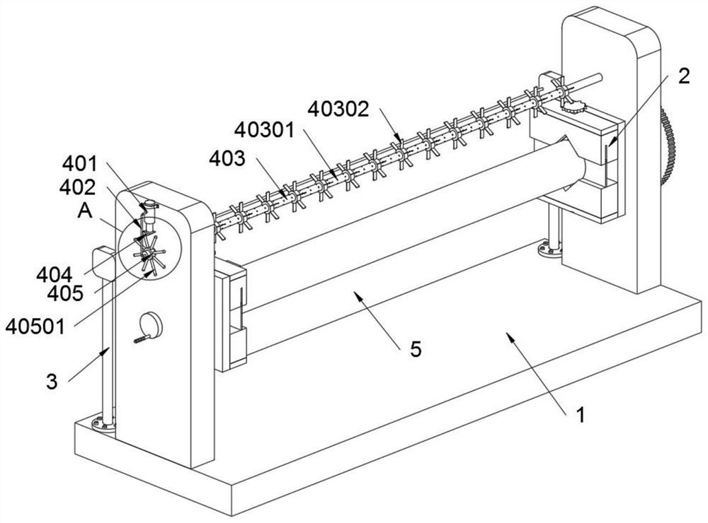
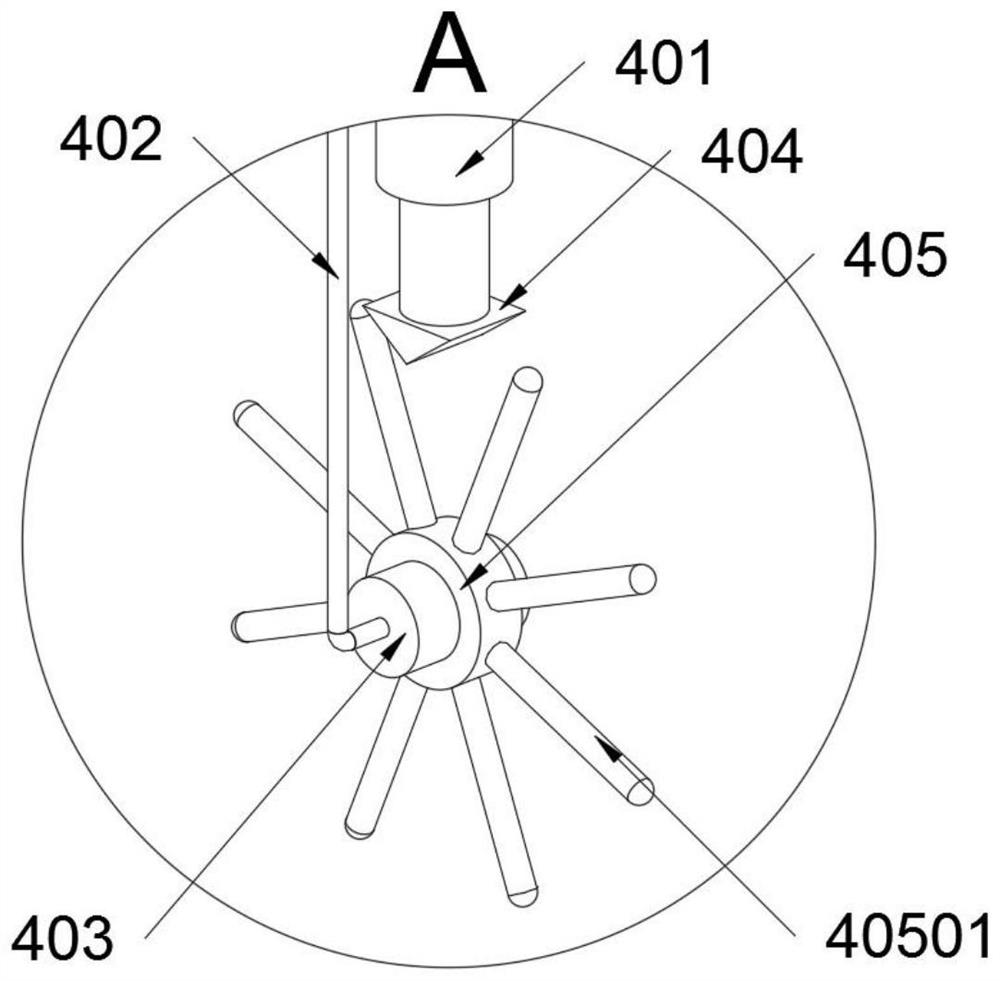
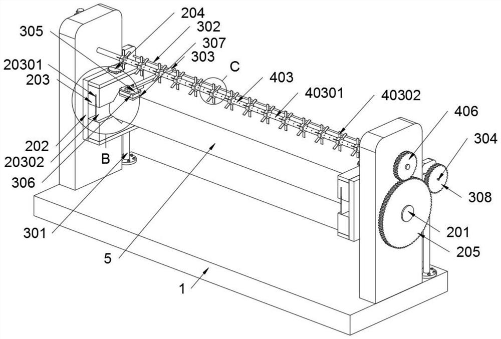
[0035]The present invention provides a pipe anticorrosion treatment equipment, which includes a main body seat 1; two clamp structures 2 are installed on the main body seat 1, and a grinding structure 3 is installed on the main body seat 1, and a pipe 5 is clamped on the clamp structure 2; An auxiliary structure 4 is installed on the main body seat 1; refer to as figure 1 with figure 2 , the auxiliary structure 4 includes a force block 404, a toggle seat 405 and a toggle bar 40501, the force block 404 is welded on the head end of the elastic telescopic bottle 401; the toggle seat 405 is installed on the nozzle pipe 403, and the toggle seat 405 Toggle lever 40501 is welded in a circular array on the top; the toggle lever 40501 is in contact with the force-bearing block 404, and the force-bearing block 404 is a triangular columnar structure, so that when the toggle seat 405 drives the toggle lever 40501 to rotate, elas...


PUM


Abstract

The invention provides a pipeline anti-corrosion treatment facility, and relates to the technical field of pipeline anti-corrosion treatment. The problems that removal of residues attached to the outer wall of a pipeline cannot be synchronously achieved after polishing operation is accomplished, displacement of a polishing structure cannot be synchronously achieved in the pipeline rotary polishingachieving process through the structural improvement, and quick clamping and collision protection of an adjusting structure cannot be achieved are solved. The pipeline anti-corrosion treatment facility comprises a body base. Two clamp structures are installed on the body base, a polishing structure is further installed on the body base, and a pipeline is clamped on the clamp structures. Due to the facts that poke rods make contact with a stress block, and the stress block is of a triangular prism structure, when a poke base drives the poke rods to rotate, continuous extrusion of an elastic telescopic bottle can be achieved. A spray pipe is connected to a connecting pipe and located at the position 5cm above the pipeline, and therefore when the elastic telescopic bottle is extruded, pneumatic removal of the polishing residues on the pipeline can be achieved through the spray pipe.

Description

technical field [0001] The invention belongs to the technical field of pipeline anticorrosion treatment, and more specifically relates to pipeline anticorrosion treatment equipment. Background technique [0002] Pipeline anticorrosion is a measure to slow down or prevent pipelines from being corroded and deteriorated under the chemical and electrochemical action of internal and external media or microbial metabolic activities. [0003] For example, the application number: CN201810573014.0, the present invention relates to a pipeline anticorrosion treatment equipment and its anticorrosion treatment process, including a bottom plate, a moving device, a rotating device, a support bracket and an auxiliary device, and the front and rear sides of the bottom plate are symmetrically equipped with moving devices , a rotating device is connected between the moving devices, an auxiliary device is arranged on the upper end of the rotating device, and a supporting bracket is arranged on ...

Claims


Application Information

Patent Timeline
Patent Type & Authority Applications(China)
IPC IPC(8): B24B5/04B24B41/02B24B41/06B24B55/06
CPCB24B5/04B24B41/02B24B41/067B24B55/06
Inventor 刘明
Owner 莱西市盈德装备技术中心
Learn More