Oxygen recovery device
A recovery device and oxygen technology, which is applied in the field of recovery equipment, can solve the problems of filter screen replacement, cost increase, oxygen tank corrosion, etc., and achieve the effects of avoiding waste, improving production efficiency, and improving recovery rate
- Summary
- Abstract
- Description
- Claims
- Application Information
AI Technical Summary
Problems solved by technology
Method used
Image

Examples
Embodiment
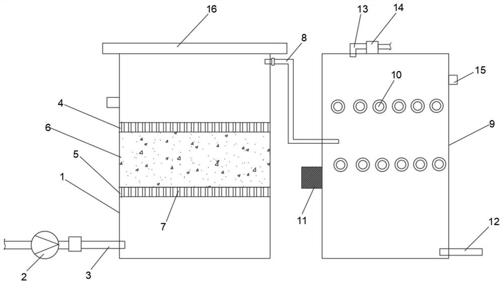
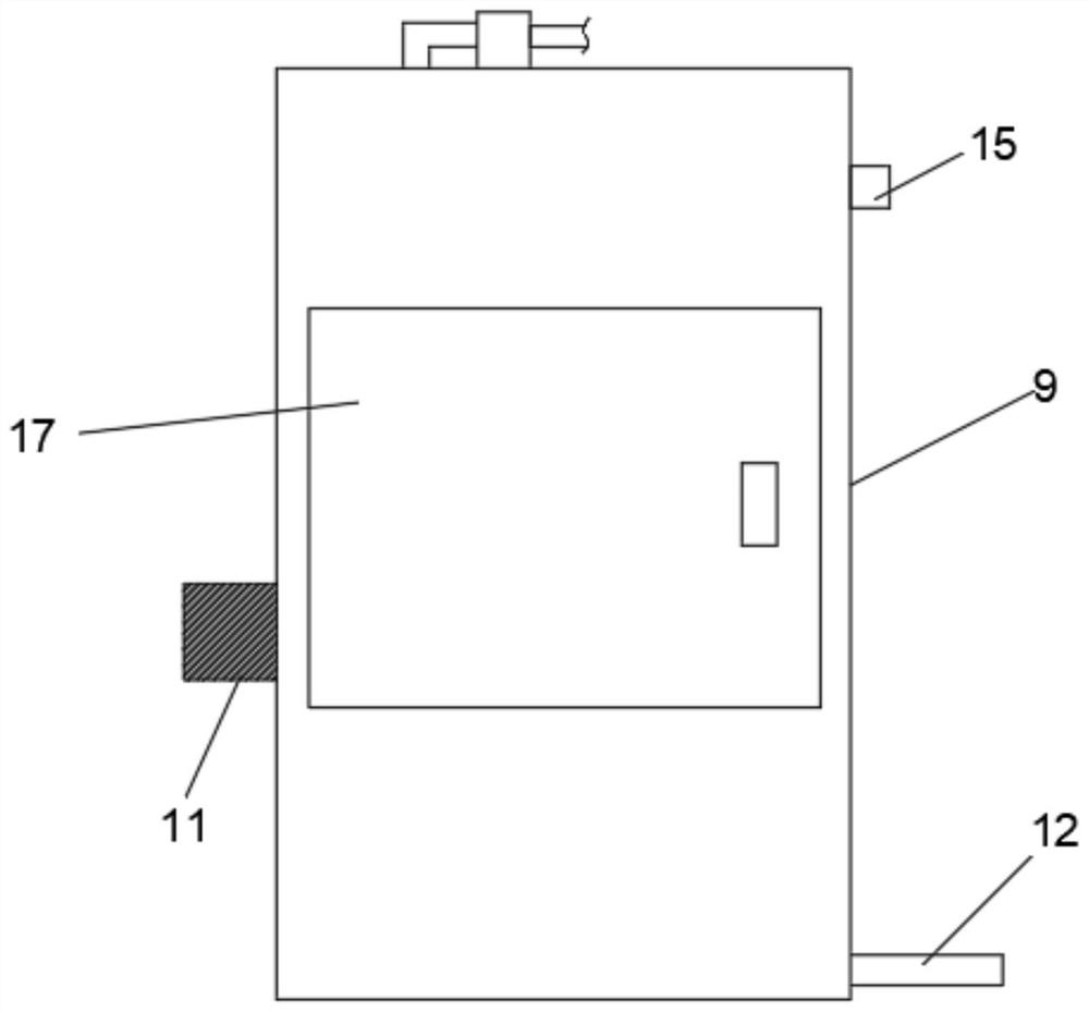
[0021] Such as Figure 1-Figure 3 As shown, the present invention provides an oxygen recovery device,
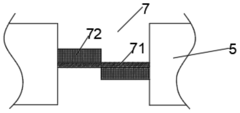
[0022] It includes a treatment box 1 and a blower 2 arranged on the lower side of the treatment box 1. The air inlet of the blower 2 is connected to an oxygen source through a pipeline, and the air outlet of the blower 2 is connected to the side of the treatment box 1 through an air inlet pipe 3. In the lower side wall, a baffle plate is detachably arranged between the inner side walls of the treatment box 1, and the baffle plate includes a first baffle plate 4 and a second baffle plate 5, and the first baffle plate 4 is located in the second baffle plate. Above the baffle plate 5, a clean chamber 6 is formed between the first baffle plate 4 and the second baffle plate 5, and graphite carbon is filled in the clean chamber 6, and the first baffle plate 4 and the second baffle plate are 5 are provided with a through hole 7, the through hole 7 is provided with a gas permeable ...
PUM
 Abstract
Description
Claims
Application Information
PatSnap Eureka turns technology decisions into work you can execute. Powered by our Innovation Knowledge Graph, it runs expert workflows across engineering, life sciences, materials and intellectual property. Get your review-ready output in minutes.


