Automatic wastewater treatment equipment and using method thereof

A technology for treating equipment and waste water, which is applied in water/sewage treatment equipment, water/sewage treatment, chemical instruments and methods, etc. It can solve problems such as inability to screen and crush large particles of impurities, poor drainage, and blockage of screens

Active Publication Date: 2021-04-02
YANTAI NANSHAN UNIV
View PDF17 Cites 0 Cited by
  • Summary
  • Abstract
  • Description
  • Claims
  • Application Information

AI Technical Summary

Problems solved by technology

[0003] The water treatment equipment currently used cannot effectively screen and crush large particles of impurities during preliminary filtration of wastewater. Large particles of impurities often block the scree...

Method used


Image

  • Automatic wastewater treatment equipment and using method thereof
  • Automatic wastewater treatment equipment and using method thereof
  • Automatic wastewater treatment equipment and using method thereof

Examples


Embodiment 1

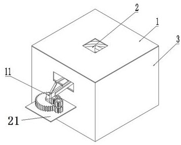
[0030] see Figure 1 to Figure 10 , The present invention provides a technical solution: an automatic treatment equipment for wastewater, which includes: a housing, a screen member 5, and a swing mechanism 11.

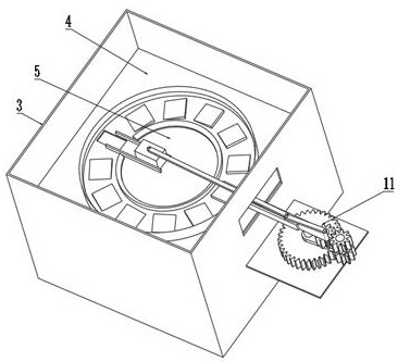
[0031] The housing includes an outer shell 3, the upper end of the outer shell 3 is fixed with a cover plate 1, the surface of the cover plate 1 is provided with a feed port 2, and a fixed plate 4 is fixedly connected with the cover plate 1 on the inner wall of the shell.

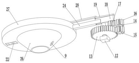
[0032] The screen member 5 includes a circular screening plate 29, the outer ring of the screening plate 29 is fixedly connected with a liquid blocking plate 28, and the outer coaxial line of the liquid blocking plate 28 is fixedly connected with a large particle impurity moving groove 30. The outer ring of the moving tank 30 is fixedly connected with the outer retaining ring 27, and the upper surface of the moving tank 30 for large particles of impurities is fixedly installed with guide blocks 6 ev...

Embodiment 2

[0049] The difference between this embodiment and Embodiment 1 lies in that the use method of an automatic treatment equipment for waste water is different.

[0050] When the trajectory of the pin shaft 25 is as Figure 6 When shown, the movement process of the device is as follows:

[0051] said Figure 6 , the arc in the circle is the motion track of pin shaft 25.

[0052] The initial state of the device is that when the pin shaft 25 is at point B2, the screen member 5 rotates to the limit position on one side of the reference line G2 direction, which is called the highest point. by Figure 4 Elaborate for the base view. Figure 6 The middle reference line G2 is an extension line of the motion track of the slide plate 8 .

[0053] The initial state of the device is that the pin shaft 25 is at point B2, and the screen member 5 rotates to the highest point.

[0054] During the movement of the pin shaft 25 from A2 to B2, the swing mechanism 11 drives the screen member 5 t...


PUM


Abstract

The invention relates to the technical field of wastewater treatment, and discloses automatic wastewater treatment equipment and a using method thereof. The equipment comprises a shell, a screen partand a swing mechanism. When liquid containing impurities enters the screen part along the feeding port, the swing mechanism enables the screen part to swing. Small-particle impurities and liquid flowout of an inner cavity of the funnel-shaped outer groove wall and enter the bottom of the outer shell, and large-particle impurities are left on the screening plate. When the swing amplitude of the screen part is large, large-particle impurities can be discharged from the liquid blocking plate and enter the large-particle impurity moving groove. And when the swing amplitude of the screen part is small, the large-particle impurities gradually migrate towards the vertical side of the guide block under the action of the guide block until the large-particle impurities move to the large-particle inlet. After large-particle impurities enter a grinding cavity formed by the outer groove wall of the screen part and the fixing plate along the large-particle inlet, when the screen part rotates, the large-particle impurities can be ground into small particles, and the small particles flow out of a cavity of the fixing plate.

Description

technical field [0001] The invention relates to the technical field of waste water treatment, in particular to automatic waste water treatment equipment and a use method thereof. Background technique [0002] Wastewater treatment is the use of physical, chemical and biological methods to treat wastewater, purify wastewater, reduce pollution, and achieve wastewater recovery and reuse, making full use of water resources. [0003] The water treatment equipment currently used cannot effectively screen and crush large particles of impurities during preliminary filtration of wastewater. Large particles of impurities often block the screen, resulting in poor drainage. In order to solve this problem, improve the efficiency of wastewater In order to improve the crushing efficiency of medium and large particle impurities, we propose an automatic wastewater treatment equipment. Contents of the invention [0004] The purpose of the present invention is to provide an automatic treatme...

Claims


Application Information

Patent Timeline
IPC IPC(8): C02F1/00B02C1/00B02C23/16B07B1/28B07B1/42
CPCB02C1/00B02C23/16B07B1/28B07B1/42C02F1/001C02F2201/002C02F2201/004C02F2303/14
Inventor 王玮刘立宁张艳涛孙艳波王雪峰苏雨龙姚彤辉马兆壮陈祥光
Owner YANTAI NANSHAN UNIV
Why Eureka
Try Eureka