Unlock instant, AI-driven research and patent intelligence for your innovation.

Depth measuring device of rotary drilling rig and rotary drilling rig

A rotary drilling rig and depth measurement technology, which is applied in the direction of measurement, drill pipe, drill pipe, etc., can solve the problems of difficult installation of sensor devices, high failure rate of sensing devices, inaccurate hole depth measurement data, etc.

Pending Publication Date: 2021-04-02
BEIJING SANY INTELLIGENT MFG TECH CO LTD
View PDF0 Cites 0 Cited by
  • Summary
  • Abstract
  • Description
  • Claims
  • Application Information

AI Technical Summary

Problems solved by technology

[0004] The first method: the measuring device is installed on the anchor bracket, the encoder is fixed to the main winch pulley, and is calculated according to the number of rotations of the pulley, but there will be counting errors when the pulley is idling, resulting in inaccurate hole depth measurement data;
[0005] The second method is: the measuring device is installed on the main winch, and the encoder is fixed on the drum to measure the number of rotations of the drum. On the one hand, the structure of the winch is compact, and the installation of the sensor device is difficult. The hole is deep, and when there are two or even three layers of wire rope on the reel, the encoder cannot measure the change of the layer of the wire rope, so that the diameter of the outer ring of the wire rope wound on the reel is always calculated with the same value, resulting in inaccurate measurement data of the hole depth;
[0006] The third way is to install the sensing device and the measuring device in the gap between the reel and the frame. However, due to the poor working condition of the rotary drilling rig and the large vibration, the sensing part of the sounding device shakes too much, which is easy to In the event of a collision, the failure rate of the induction device is relatively high, and the drilling depth cannot be accurately measured

Method used


Image

  • Depth measuring device of rotary drilling rig and rotary drilling rig
  • Depth measuring device of rotary drilling rig and rotary drilling rig
  • Depth measuring device of rotary drilling rig and rotary drilling rig

Examples


Embodiment Construction

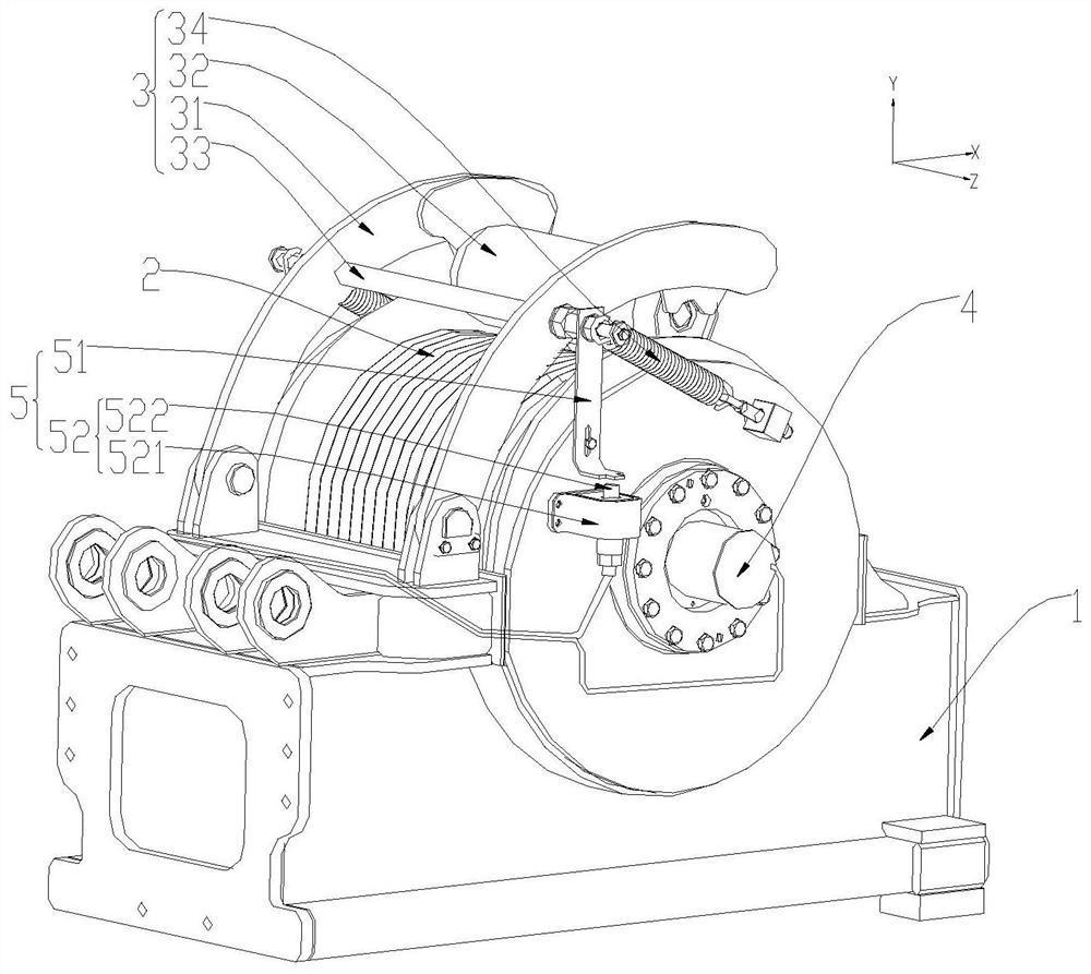
[0039] Rotary drilling rig is a construction machine suitable for hole-forming operations in building foundation engineering, and is widely used in various foundation constructions such as cast-in-place piles and foundation reinforcement. At present, there are strict requirements on the drilling depth of rotary drilling rigs, and it is generally necessary to monitor the hole depth data in real time during construction. However, in the prior art, the depth measuring device of the rotary drilling rig has poor structural stability and inaccurate measurement.

[0040] The technical solutions in the embodiments of the present application will be described clearly and in detail below in conjunction with the accompanying drawings. In the description of the present invention, it should be understood that the positive direction of "X" in the drawings represents the right, the reverse of "X" represents the left, the positive direction of "Y" represents the top, and the reverse of "Y" Re...


PUM


Abstract

The invention provides a depth measuring device of a rotary drilling rig and the rotary drilling rig, and belongs to the technical field of engineering machinery. The depth measuring device of the rotary drilling rig comprises a pressing cylinder structure, a first measuring structure and a second measuring structure, wherein the pressing cylinder structure is suitable for being elastically connected with a winding drum structure used for winding a winding rope and suitable for being hinged to a frame body used for supporting the winding drum structure; the first measuring structure is connected with the winding drum structure and used for detecting the number of rotating turns of the winding drum structure; and the second measuring structure is connected with the pressing cylinder structure and is suitable for being connected with the frame body, and the second measuring structure is used for detecting the overall thickness change condition of the winding rope wound on the winding drum structure. The depth measuring device of the rotary drilling rig is accurate in drilling depth measurement data, simple in structure, convenient to disassemble and assemble and long in service life.

Description

technical field [0001] The invention relates to the technical field of engineering machinery, in particular to a depth measuring device of a rotary drilling rig and the rotary drilling rig. Background technique [0002] Rotary drilling rig is a construction machine suitable for hole-forming operations in building foundation engineering, and is widely used in various foundation constructions such as cast-in-place piles and foundation reinforcement. [0003] In the prior art, there are strict requirements on the drilling depth of the rotary drilling rig, and it is generally necessary to monitor the hole depth data in real time during construction. At present, the following methods are generally used: [0004] The first method: the measuring device is installed on the anchor bracket, the encoder is fixed to the main winch pulley, and is calculated according to the number of rotations of the pulley, but there will be counting errors when the pulley is idling, resulting in inaccu...

Claims


Application Information

Patent Timeline
IPC IPC(8): E21B47/04E21B19/00
CPCE21B19/008E21B19/00E21B47/04Y02A90/30
Inventor 陈红王鹏程景芬
Owner BEIJING SANY INTELLIGENT MFG TECH CO LTD