An energy-saving and environment-friendly vehicle exhaust gas treatment device

A technology of automobile exhaust and treatment device, which is applied in the direction of exhaust device, exhaust gas treatment, muffler device, etc., can solve the problem of inability to treat solid suspended particles, and achieve the effect of environmental protection and convenient operation.

Active Publication Date: 2021-11-09
JIANGXI COLLEGE OF APPLIED TECH
View PDF8 Cites 0 Cited by
  • Summary
  • Abstract
  • Description
  • Claims
  • Application Information

AI Technical Summary

Problems solved by technology

[0004] In order to overcome the disadvantage that the existing three-way catalytic converter cannot process the solid suspended particles in the automobile exhaust, the technical problem of the present invention is to provide an energy-saving and environment-friendly automobile that can automatically filter the particles in the exhaust gas and purify the exhaust gas. Exhaust gas treatment device

Method used


Image

  • An energy-saving and environment-friendly vehicle exhaust gas treatment device
  • An energy-saving and environment-friendly vehicle exhaust gas treatment device
  • An energy-saving and environment-friendly vehicle exhaust gas treatment device

Examples


Embodiment 1

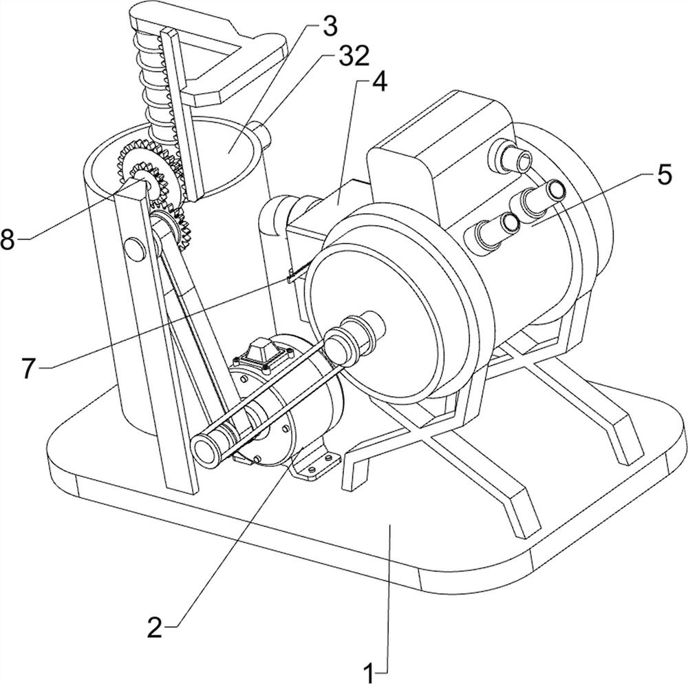
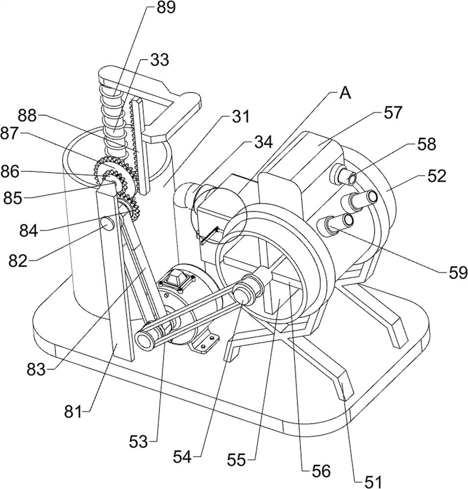
[0071] A kind of energy-saving and environment-friendly automobile tail gas treatment device, such as figure 1 , figure 2 and image 3As shown, it includes a base plate 1, a motor 2, a storage mechanism 3, a filter mechanism 4 and a stirring mechanism 5. The motor 2 is provided on the front side of the top of the base plate 1, the storage mechanism 3 is provided on the left side of the top of the base plate 1, and the storage mechanism 3 is provided on the right side of the top of the base plate 1. There is a stirring mechanism 5, and a filtering mechanism 4 is arranged between the storage mechanism 3 and the stirring mechanism 5.

[0072] The storage mechanism 3 includes a storage cylinder 31, a one-way air inlet 32, a pressure rod 33 and a one-way air outlet pipe 34. The storage cylinder 31 is provided on the left side of the top of the bottom plate 1, and a one-way air inlet is provided on the upper rear side of the storage cylinder 31. 32. The inside of the storage cyli...

Embodiment 2

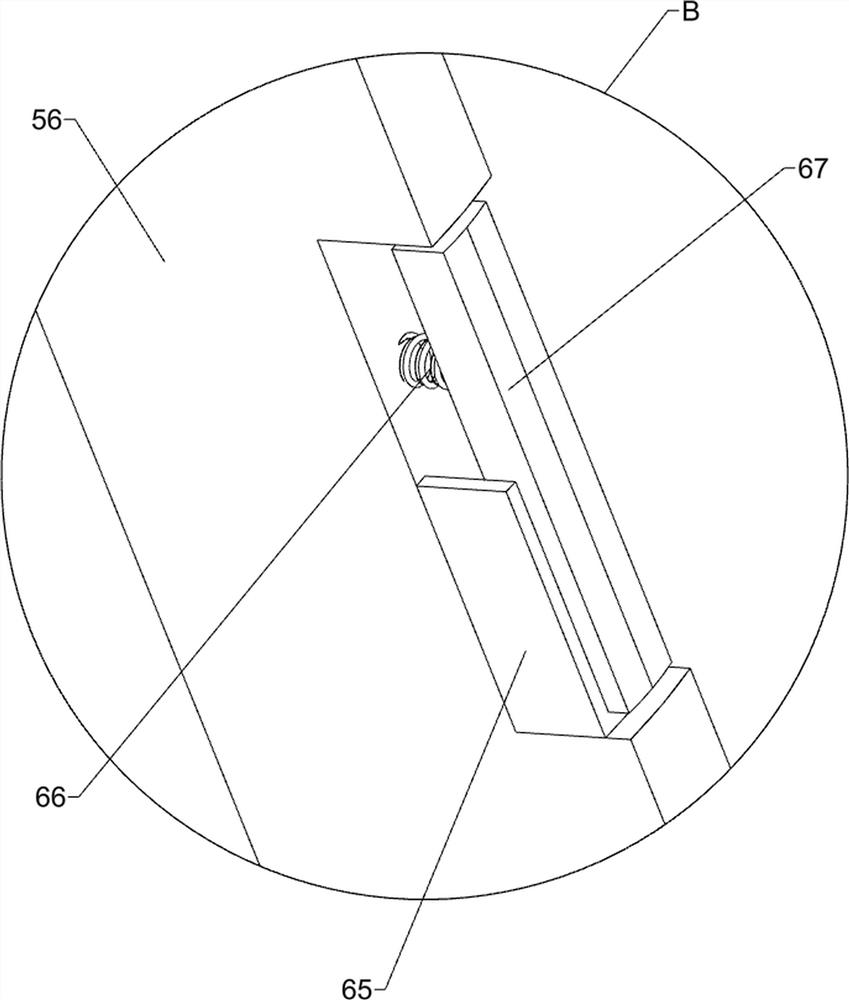
[0077] On the basis of Example 1, such as figure 2 , image 3 , Figure 4 and Figure 5 As shown, an indirect blanking mechanism 6 is also included, and the indirect blanking mechanism 6 includes a movable plate 61, a first top block 62, a first spring 63, a second top block 64, a fixed seat 65, a second spring 66 and a second top block. Three top blocks 67, the top of the outer cylinder 52 is slidingly provided with a movable plate 61, the movable plate 61 blocks the bottom of the liquid storage box 57, the right side of the bottom of the movable plate 61 is provided with a first top block 62, and the front and rear sides of the right side of the movable plate 61 The first spring 63 is arranged between the outer cylinder 52, the second top block 64 is symmetrically arranged on the top of the inner side of the outer cylinder 52, and the second rotating plate 56 is equipped with a fixed seat 65 on the outer side of the second rotating plate 56. There is a third jacking bloc...


PUM


Abstract

The invention relates to a tail gas treatment device, in particular to a vehicle tail gas treatment device for energy saving and environmental protection. The technical problem of the present invention is to provide an energy-saving and environment-friendly vehicle exhaust gas treatment device that can automatically filter the particles in the exhaust gas and purify the exhaust gas. The invention provides such an energy-saving and environment-friendly automobile exhaust treatment device, which comprises a bottom plate and a motor, a motor is provided on the top side of the bottom plate; a storage mechanism is provided on the top side of the bottom plate; a stirring mechanism is provided on the top side of the bottom plate Stirring mechanism. The present invention can automatically filter and purify the automobile tail gas through the cooperation of the storage mechanism, the filtering mechanism and the stirring mechanism, and turn the automobile tail gas into non-toxic emission, which is convenient to operate and environmentally friendly; through the indirect feeding mechanism, the intermittent catalyst can be automatically completed Automatic cutting, no need to manually add catalysts, which is convenient for people's work.

Description

technical field [0001] The invention relates to a tail gas treatment device, in particular to a vehicle tail gas treatment device for energy saving and environmental protection. Background technique [0002] Automobile exhaust is the exhaust gas generated when the vehicle is in use. It contains hundreds of different compounds. The pollutants include solid suspended particles, carbon monoxide, carbon dioxide, hydrocarbons, nitrogen oxides, lead and sulfur oxides. Exhaust gas not only directly endangers human health, but also has a profound impact on the environment in which human beings live. [0003] At present, in order to protect the environment, a three-way catalytic converter is installed in the automobile exhaust system to purify the exhaust gas emitted by the automobile into non-toxic gas, but the solid suspended particles in the exhaust gas will still be discharged into the air, causing smog, etc. The weather affects people's lives. Therefore, an energy-saving and en...

Claims


Application Information

Patent Timeline
Patent Type & Authority Patents(China)
IPC IPC(8): F01N3/021F01N3/20F01N3/28F01N3/023
CPCF01N3/021F01N3/0232F01N3/206F01N3/28F01N2240/26F01N2250/02Y02A50/20
Inventor 姜云斐吴金华邓方
Owner JIANGXI COLLEGE OF APPLIED TECH
Why Eureka
Try Eureka