Defect area calculation method and system for pipeline detection

A technology for pipeline detection and defect area, which is applied in the direction of optical testing of flaws/defects, measuring devices, and optical devices. It can solve the problems of pipe center deviation, pipeline data distortion, and quantization errors, etc., and achieve simple calculation principles and calculation The results are precise

Active Publication Date: 2021-04-02
WUHAN EASY SIGHT TECH
View PDF6 Cites 0 Cited by
  • Summary
  • Abstract
  • Description
  • Claims
  • Application Information

AI Technical Summary

Problems solved by technology

[0004] However, in the existing technology, defect assessment is performed based on video or image data. This method mostly relies on personal experience for the amount of pipeline defects, which may easily lead to a large deviation between the actual quantified data and the actual defect data. In addition, the two-dimensional laser radar point cloud data is used to During

Method used


Image

  • Defect area calculation method and system for pipeline detection
  • Defect area calculation method and system for pipeline detection
  • Defect area calculation method and system for pipeline detection

Examples


Example Embodiment

[0034]The present invention will be further described below in conjunction with the embodiments to make those skilled in the art with reference to the specification.

[0035]It should be noted that in the description of the present invention, the term "horizontal", "longitudinal", "upper", "lower", "front", "post", "left", "right", "vertical", The orientation relationship between "horizontal", "top", "bottom", "inside", "outside", etc. is based on the orientation or positional relationship shown in the drawings, only for convenience of description of the present invention and simplified description, and It is not an instruction or suggest that the device or component must have a specific orientation, constructed and operated in a particular direction, and thus is not to be construed as limiting the invention.
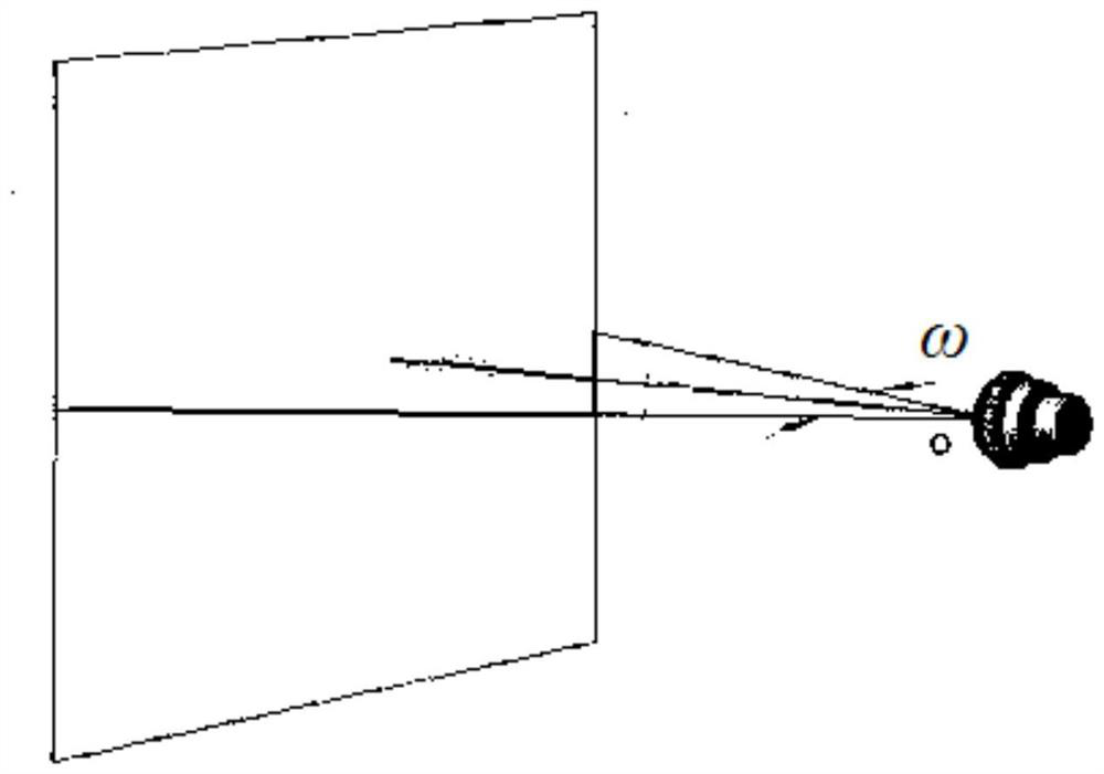
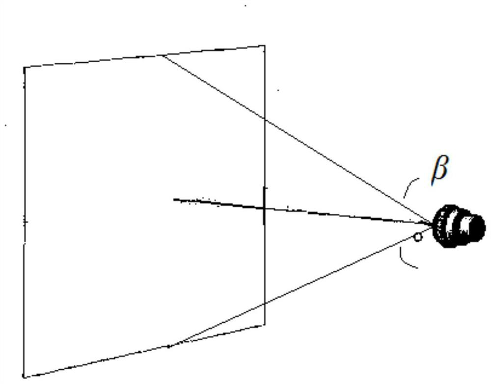
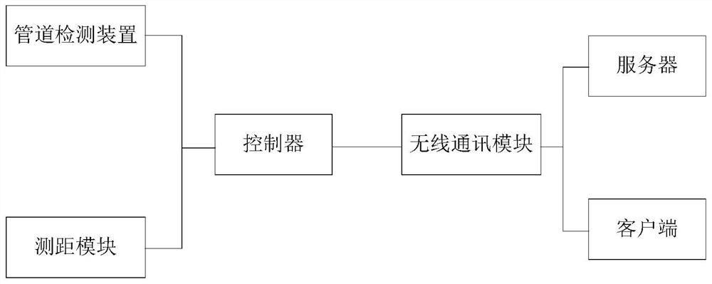
[0036]Such asFigure 1 - Figure 2As shown, embodiments of the present invention provide a method of calculating a defective area for pipe detection, including:

[0037]Through the came...


PUM


Abstract

The invention discloses a defect area calculation method and system for pipeline detection. The method comprises the following steps: obtaining the image information of a part, with a structural defect, in a pipeline through a camera, and obtaining a horizontal field angle omega and a vertical field angle beta of the camera and the distance S between the camera and the position, with the structural defects, in the pipeline during photographing; and according to the horizontal view field angle omega, the vertical view field angle beta, the distance S between the camera and the position where the structural defect occurs in the pipeline, and the ratio of the resolution corresponding to the defect position in the image information to the resolution of the image information, calculating to obtain the actual area of the defect position of the pipeline in the image information. According to the defect area calculation method and system for pipeline detection, the calculation principle is simple and convenient, and the calculation result is accurate.

Description

technical field [0001] The invention relates to the field of pipeline detection. More specifically, the present invention relates to a defect area calculation method and system for pipeline detection. Background technique [0002] At present, the inspection of the pipeline network mainly consists of inspection robots crawling on the bottom of the pipeline, monitoring the pipeline by obtaining video information, discovering functional defects of the pipeline, and performing pipeline maintenance; evaluating structural defects for pipeline repair. [0003] In the existing technology, the evaluation of structural defects in pipelines often takes video and screenshots of the damaged locations in the pipelines based on the camera mounted on the robot to obtain structural defect data in the pipelines, or through two-dimensional laser radar Scan the pipeline cross-section during the pipeline robot's travel, and reconstruct the pipeline's three-dimensional data according to the rada...

Claims


Application Information

Patent Timeline
IPC IPC(8): G01B11/28G01N21/88
CPCG01B11/285G01N21/8851
Inventor 刘志国彭庚翟樨祚
Owner WUHAN EASY SIGHT TECH
Why Eureka
Try Eureka