Eureka AIR delivers breakthrough ideas for toughest innovation challenges, trusted by R&D personnel around the world.

Deformation plenum chamber for supersonic wind tunnel test

A wind tunnel test and supersonic technology, which is applied in the field of supersonic wind tunnels and deformation chambers, can solve the problems of broken pin shafts, unusable sealing methods, and unsatisfactory use requirements, etc., and achieves good sealing effect, simple structure, and space-saving The effect of chamber pressure and sealing problems

Active Publication Date: 2021-04-02
中国空气动力研究与发展中心设备设计及测试技术研究所
View PDF6 Cites 3 Cited by
  • Summary
  • Abstract
  • Description
  • Claims
  • Application Information

AI Technical Summary

Problems solved by technology

However, the aforementioned method has the following problems: first, when installing and debugging on site, considering that the nozzle section will push the test section to move towards the super-expansion section due to the load during the experiment, and the nozzle section will return to its original position after the test. Fixing the small resident chamber on the nozzle section may damage the pin shaft; secondly, the traditional seal is to realize the sealing function by compressing the deformation of the rubber. Due to the experimental requirements, the movable resident chamber needs to be repeatedly raised and lowered. Due to the limitation of the slotting space of the nozzle section, traditional rubber gaskets or rubber sealing rods cannot meet the needs of use; third, due to the structural shape characteristics and movement requirements of the movable chamber, its sealing method cannot be conventional end flange sealing or flat surface sealing. Inflatable sealing requires a space combined dynamic sealing structure

Method used


Image

  • Deformation plenum chamber for supersonic wind tunnel test
  • Deformation plenum chamber for supersonic wind tunnel test
  • Deformation plenum chamber for supersonic wind tunnel test

Examples


Embodiment Construction

[0042] The technical solutions of the various embodiments of the present invention will be clearly and completely described below in conjunction with the accompanying drawings. Apparently, the described embodiments are only some of the embodiments of the present invention, not all of them. Based on the embodiments of the present invention, all other embodiments obtained by persons of ordinary skill in the art without making creative efforts belong to the protection scope of the present invention.

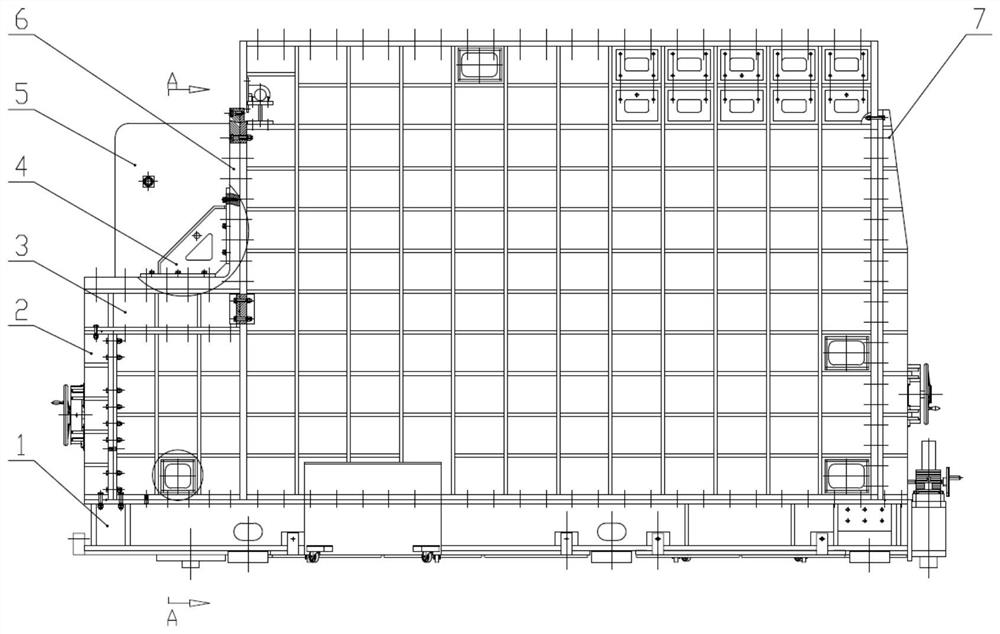
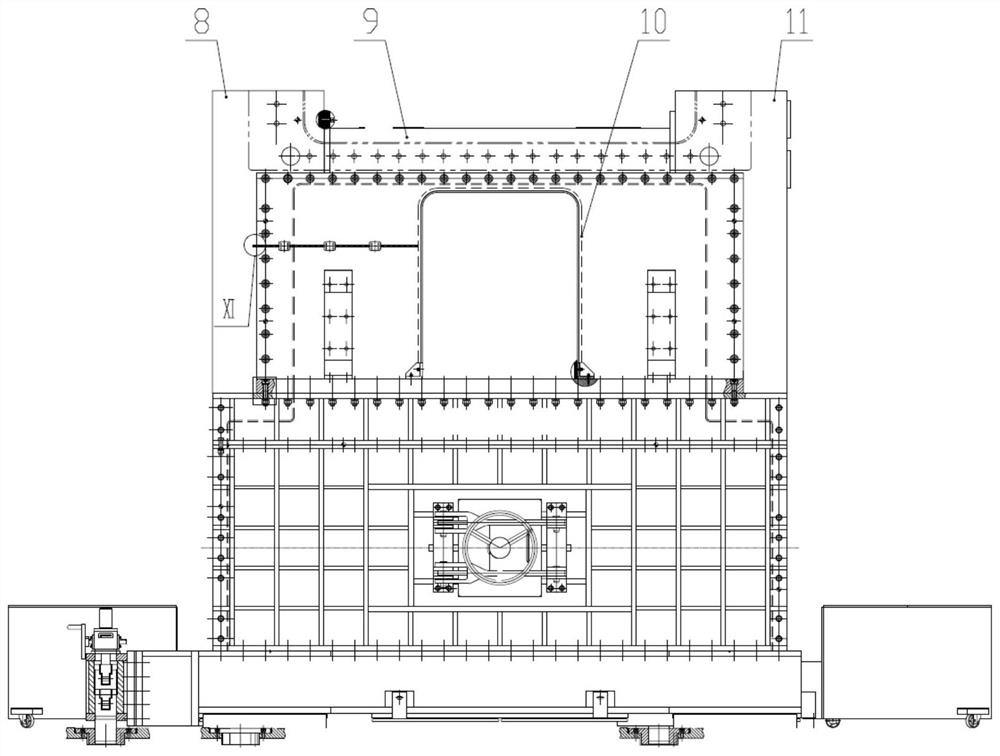
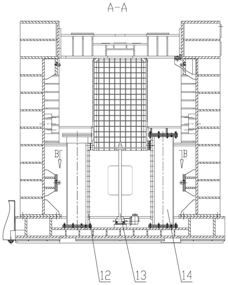
[0043] In this embodiment, the deformation chamber used for the supersonic wind tunnel test is as follows Figure 1-3 As shown, it includes a fixed resident chamber, a support 4 , a movable resident chamber 5 , an L-shaped flange 6 , an inflatable sealing ring 10 , a sliding assembly 12 and a screw jack 13 .

[0044] Such as Figure 1-2 As shown, the fixed resident chamber has a rectangular parallelepiped hollow structure, including the resident chamber body. One end of the residen...


PUM


Abstract

The invention discloses a deformation plenum chamber for a supersonic wind tunnel test. The deformation plenum chamber comprises a fixed plenum chamber, a movable plenum chamber, a spiral elevator, asliding assembly, a connecting flange and an inflatable sealing ring; the fixed plenum chamber is provided with a connecting end surface with an L-shaped ring-shaped structure; a window is formed in the connecting flange, and a sealing groove is formed in the side wall of the window; the inflatable sealing ring comprises a sealing ring body and an inflation pipe which are integrally formed, and the sealing ring body is installed in the sealing groove; the sliding assembly and the spiral elevator are installed in an inner cavity of the plenum chamber body, the connecting flange is fixedly connected with the connecting end face of the plenum chamber body, and the spiral elevator controls the movable plenum chamber to move up and down in the vertical direction under the action of the slidingassembly. The deformation plenum chamber effectively solves the problem of sealing of a cavity formed when an attack angle mechanism moves, bears differential pressure formed when a flow field is established, meanwhile solves the problem that the slotting space of a flexible spray pipe section is limited when a throwing test section is in place, and improves the experiment efficiency.

Description

technical field [0001] The invention belongs to the technical field of wind tunnel test equipment, and relates to a supersonic wind tunnel, in particular to a deformation chamber used for supersonic wind tunnel tests. Background technique [0002] "High speed" and "precision" of aircraft is an extremely important development direction of aircraft in the 21st century, and it is an effective means to improve the performance of aircraft. The development of advanced aircraft strongly depends on the ground simulation test equipment - wind tunnel. Simulation tests carried out in wind tunnels are called wind tunnel tests. Simply put, the wind tunnel test is based on the principle of relativity of motion, fixing the model or object of the aircraft in an artificial environment on the ground, artificially creating airflow to simulate various complex flight states in the air, and obtaining test data. This is the "green channel" for the development and production of modern aircraft, mi...

Claims


Application Information

Patent Timeline
Patent Type & Authority Applications(China)
IPC IPC(8): G01M9/04
CPCG01M9/04
Inventor 王睿邱荣凯高鑫宇刘秉斌蔡清青陈万华
Owner 中国空气动力研究与发展中心设备设计及测试技术研究所
Why Eureka
Eureka Blog
Learn More