Eutectic welding equipment for chip

A eutectic soldering and chip technology, which is applied in the manufacture of electrical components, electrical solid devices, semiconductor/solid devices, etc., can solve problems such as inability to clean and collect, achieve cleaning and maintenance, avoid waste of tin, and reduce processing costs Effect

Active Publication Date: 2021-04-02
无锡英诺赛思科技有限公司
View PDF11 Cites 3 Cited by
  • Summary
  • Abstract
  • Description
  • Claims
  • Application Information

AI Technical Summary

Problems solved by technology

[0009] The purpose of the present invention is to provide a chip eutectic welding equipment to solve the problem in the above-mentioned background technology that the excessive tin on the chip cannot be cleaned and collected

Method used


Image

  • Eutectic welding equipment for chip
  • Eutectic welding equipment for chip
  • Eutectic welding equipment for chip

Examples


Embodiment 1

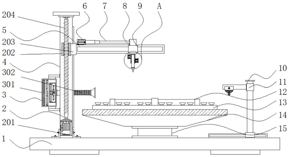
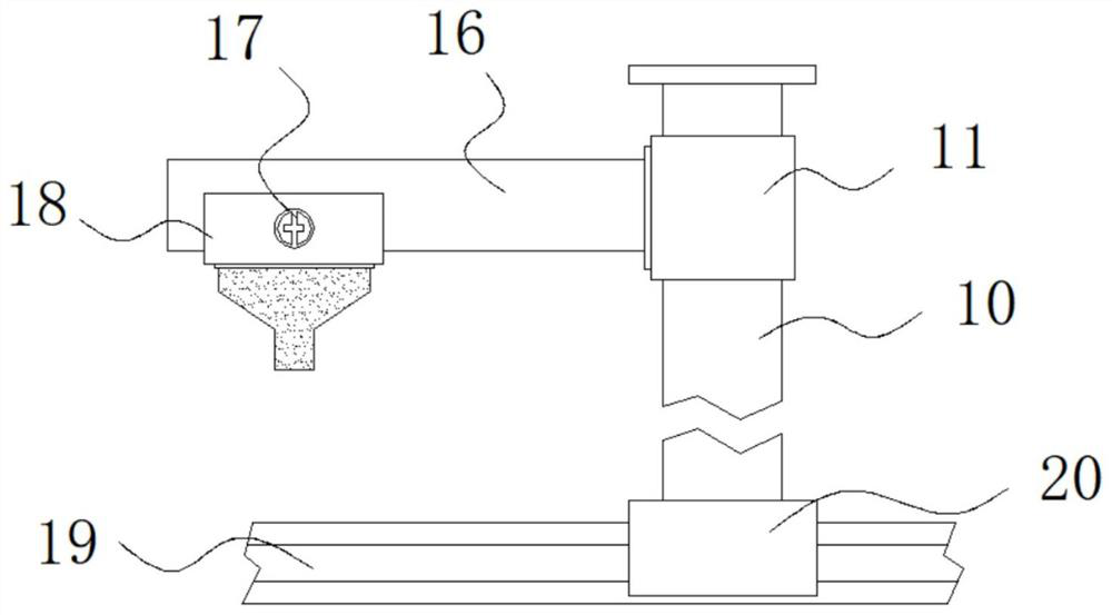
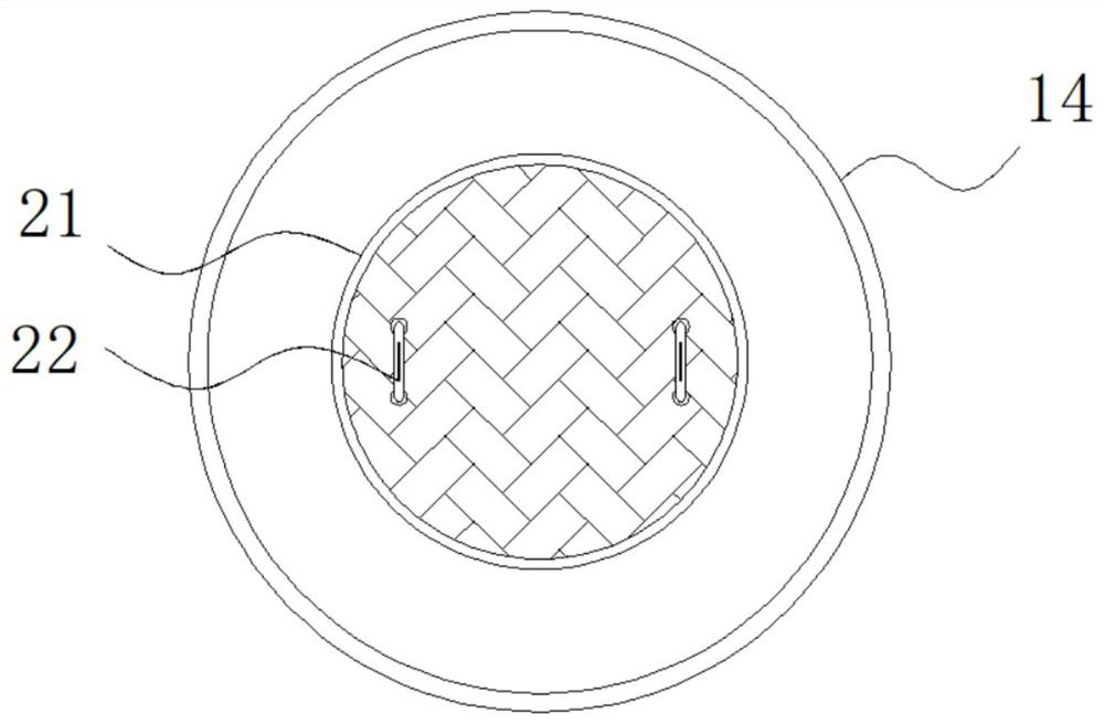
[0035] Example 1: See Figure 1-6, a chip eutectic welding equipment, including a base 1 and a column 4, one side of the top of the base 1 is fixedly connected with a column 4, the interior of the column 4 is provided with an adjustment mechanism 2, and one side of the column 4 is fixedly connected with a dust suction mechanism 3 , the other side of the column 4 is provided with a cross bar 5, one side of the top of the cross bar 5 is fixedly connected with an electric push rod 6, the model of the electric push rod 6 is IP800, and the output end of the electric push rod 6 is fixedly connected with a telescopic rod 7. One end of the crossbar 5 is provided with a first slider 8, the bottom end of the first slider 8 is fixedly connected with a replacement structure 9, the top end of the base 1 is fixedly connected with a rotating shaft 15, and the top end of the rotating shaft 15 is fixedly connected with a collecting tray 14 , the top of the collection tray 14 is provided with a...

Embodiment 2

[0040] Embodiment 2: Adjusting mechanism 2 is made up of servo motor 201, driving block 202, connecting block 203 and threaded rod 204, and threaded rod 204 is arranged on the inside of column 4, and the bottom end of threaded rod 204 is fixedly connected with servo motor 201, and this servo The model of the motor 201 is FLSC-67, the external movable part of the threaded rod 204 is connected with the driving block 202, and one side of the driving block 202 is fixedly connected with the connecting block 203;

[0041] One side of the connection block 203 is fixedly connected to one side of the cross bar 5, and the output end of the servo motor 201 is fixedly connected to the bottom end of the threaded rod 204 through a coupling;

[0042] Specifically, such as figure 1 As shown, since the device needs to process and weld different chips, the servo motor 201 at the bottom end of the column 4 is used to drive the threaded rod 204 to perform forward and reverse rotation, and the dri...

Embodiment 3

[0043] Embodiment 3: Dust suction mechanism 3 is made up of dust collection box 301, dust suction pipe 302, filter screen 303, filter agent 304 and blower fan 305, and dust collection box 301 is fixedly connected on one side of column 4, and the inside of dust collection box 301 One side is fixedly connected with a fan 305, the model of the fan 305 is DF, the other side inside the dust box 301 is fixedly connected with a filter screen 303, the inside of the dust box 301 is fixedly connected with a filter 304, and the inside of the dust box 301 One side is fixedly connected with a dust suction pipe 302;

[0044] One side of the dust suction pipe 302 runs through one side of the dust collecting box 301 and is fixedly connected to the input end of the fan 305;

[0045] Specifically, such as figure 1 with Figure 4 As shown, a specific solder paste is needed when soldering the chip, and the solder paste will produce some pungent gases during processing. By installing a dust box ...


PUM


Abstract

The invention discloses chip eutectic welding equipment and particularly relates to the technical field of chip processing. The chip eutectic welding equipment comprises a base and a stand column, wherein one side of the top end of the base is fixedly connected with the stand column, an adjusting mechanism is arranged in the stand column, one side of the stand column is fixedly connected with a dust collection mechanism, and the other side of the stand column is provided with a cross rod. By arranging the sliding groove, the adjusting block, the suction cups, the baffle and the center shaft, corners of a chip are prone to being damaged when the chip is clamped and fixed through a traditional welding device, the multiple sets of suction cups are installed at the top end of the workbench used for machining, and the chip is placed at the top ends of the suction cups and then slightly pressed downwards; the chip can be stably placed on the sucking disc, the angle between the baffles outside the center shaft can be adjusted according to the widths of different chips, the angles of the baffles can be adjusted by moving the adjusting blocks, and therefore the situation that corners are damaged due to the fact that the chip is clamped by hard objects can be avoided by fixing the chip.

Description

technical field [0001] The invention relates to the technical field of chip processing, in particular to a chip eutectic welding device. Background technique [0002] Chip processing needs to be packaged and welded. The existing packaging and welding technology includes eutectic welding technology. Eutectic welding technology has the advantages of fast heat transfer and strong adhesion, so it is the most widely used electronic packaging technology. The eutectic soldering technology still has some deficiencies when it is used. For example, when the chip is soldered, sometimes there is too much tin, and some tin remains on the surface of the chip during soldering and cannot be cleaned, or the soldering head of the device used for soldering cannot be cleaned. Disassemble and replace, once the welding head fails, the whole device cannot be used. [0003] In the process of realizing the present invention, the inventors have found that at least the following problems in the prior...

Claims


Application Information

Patent Timeline
Patent Type & Authority Applications(China)
IPC IPC(8): H01L21/60H01L21/683H01L21/687B08B1/00B08B5/04
CPCH01L24/75H01L24/81B08B1/005B08B5/04H01L21/6838H01L21/68785H01L2224/75841H01L2224/81912H01L2224/81805H01L2224/7501
Inventor 周德金马君健徐宏钟磊刘宗伟于理科
Owner 无锡英诺赛思科技有限公司
Why Eureka
Try Eureka