
Light emitting device and display panel

A technology for light-emitting devices and light-emitting layers, applied in the manufacturing of semiconductor devices, electric solid-state devices, semiconductor/solid-state devices, etc. The effect of increasing the degree of shift, improving the luminous efficiency, and increasing the range of the film layer

Pending Publication Date: 2021-04-02
KUNSHAN GO VISIONOX OPTO ELECTRONICS CO LTD
View PDF3 Cites 0 Cited by
  • Summary
  • Abstract
  • Description
  • Claims
  • Application Information

AI Technical Summary

Problems solved by technology

[0003] Due to the different transport rates of electrons and holes in organic materials, the number of electrons and holes in the light-emitting layer is not equal, and the recombination centers of electrons and holes will shift to the electrode side; Dismantling of large energy level difference leads to luminescence quenching and affects luminous efficiency

Method used


Image

  • Light emitting device and display panel
  • Light emitting device and display panel
  • Light emitting device and display panel

Examples


Embodiment Construction

[0036] The characteristics and exemplary embodiments of various aspects of the present invention will be described in detail below. In order to make the purpose, technical solutions and advantages of the present invention clearer, the present invention will be further described in detail below in conjunction with the accompanying drawings and specific embodiments. It should be understood that the specific embodiments described here are only configured to explain the present invention, not to limit the present invention. It will be apparent to one skilled in the art that the present invention may be practiced without some of these specific details. The following description of the embodiments is only to provide a better understanding of the present invention by showing examples of the present invention.

[0037] It should be noted that in this article, relational terms such as first and second are only used to distinguish one entity or operation from another entity or operation...


PUM

PropertyMeasurementUnit
Thicknessaaaaaaaaaa

Abstract

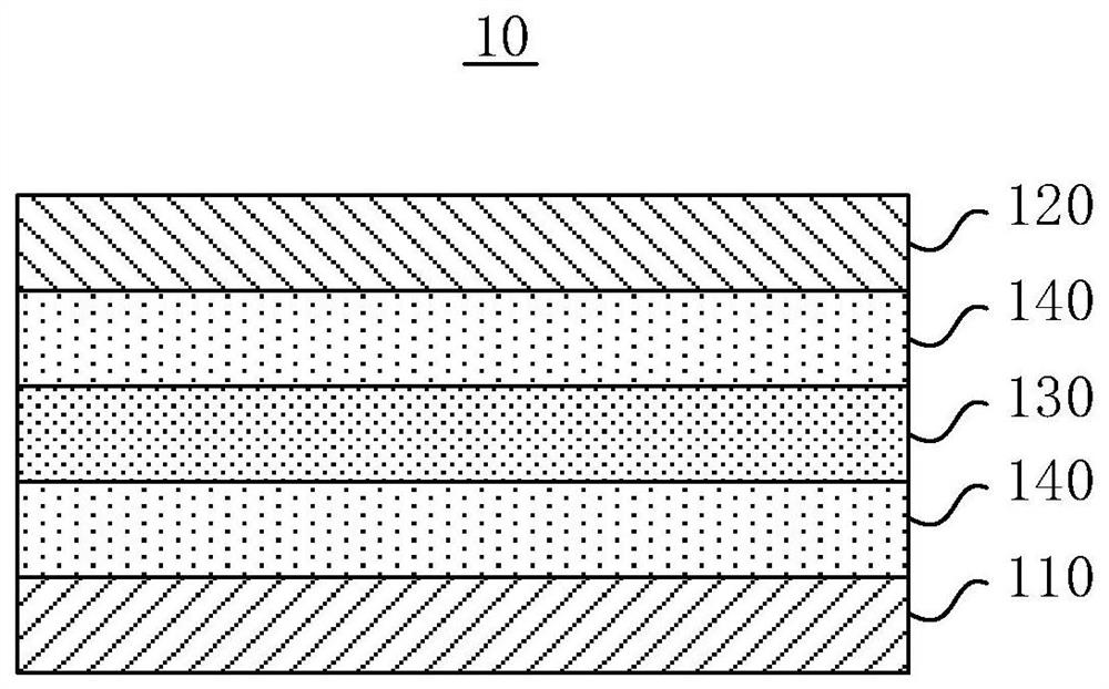
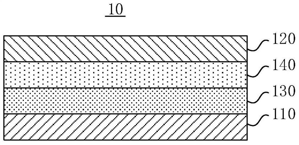
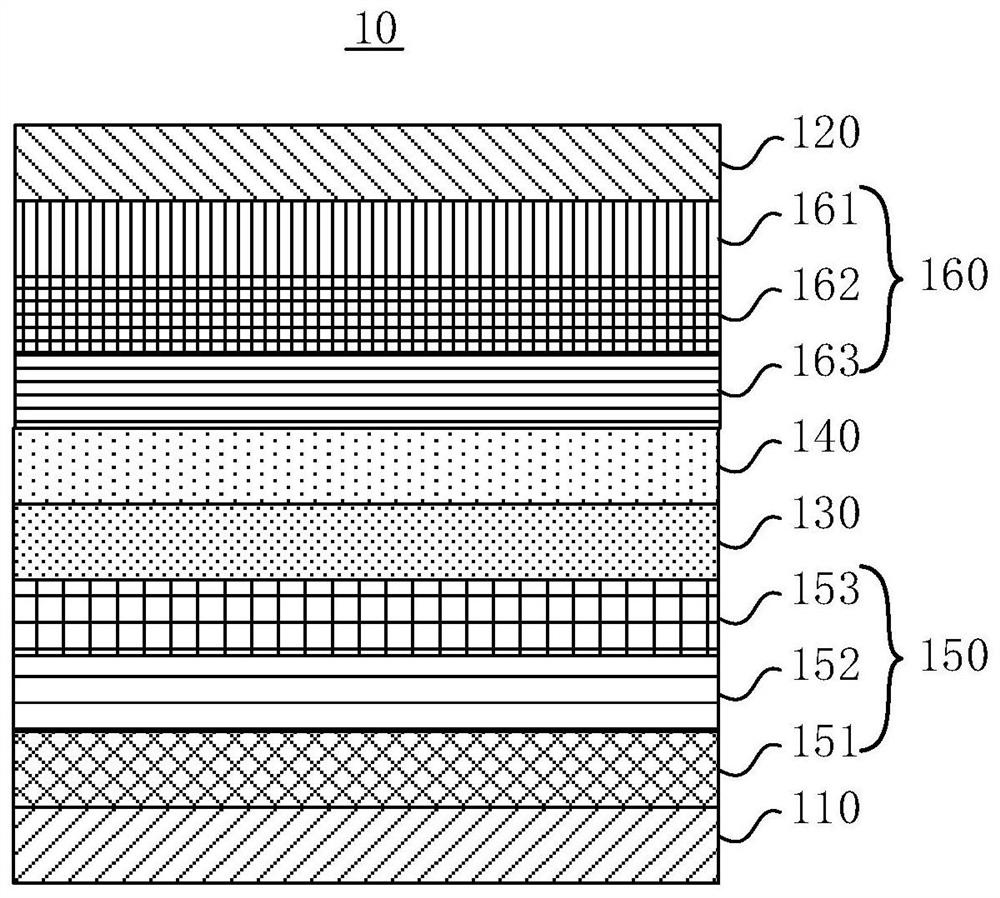
The invention discloses a light emitting device and a display panel. The light emitting device comprises a first electrode, a second electrode, a light-emitting layer arranged between the first electrode and the second electrode, including a first host material and a guest material, and having a side facing the first electrode and a side facing the second electrode, and an auxiliary light-emittinglayer arranged on at least one side of the light-emitting layer; and the auxiliary light-emitting layer material and the first host material are light-emitting host materials used for light-emittingdevices of the same color. The light emitting efficiency of the light emitting device can be improved.

Description

technical field [0001] The invention relates to the field of display technology, in particular to a light emitting device and a display panel. Background technique [0002] Organic Light-Emitting Diode (OLED) is an electroluminescent device based on organic materials. Its basic structure includes an anode, a cathode and a light-emitting layer. When a voltage is applied to the anode and the cathode, the effect of the electric field Next, the holes generated by the anode and the electrons generated by the cathode migrate to the light-emitting layer. When the two meet in the light-emitting layer, they combine to generate excitons, which excite the light-emitting molecules to generate visible light. [0003] Due to the different transport rates of electrons and holes in organic materials, the number of electrons and holes in the light-emitting layer is not equal, and the recombination centers of electrons and holes will shift to the electrode side; The dismantling of the large ...

Claims


Application Information

Patent Timeline
IPC IPC(8): H01L51/50H01L27/32
CPCH10K59/10H10K50/12H10K50/11
Inventor 刘俊伟颜志敏苏圣勋李灏刘强孟辉辉刘亚伟覃鸿胜
Owner KUNSHAN GO VISIONOX OPTO ELECTRONICS CO LTD
Learn More