Camera module and assembly method thereof

The technology of a camera module and assembly method, which is applied in the field of photography, can solve the problems affecting the focusing accuracy and anti-shake accuracy of the camera module, and affecting the appearance, etc.

Active Publication Date: 2021-04-30
TRULY OPTO ELECTRONICS
View PDF15 Cites 0 Cited by
  • Summary
  • Abstract
  • Description
  • Claims
  • Application Information

AI Technical Summary

Problems solved by technology

[0002] like figure 1 As shown, in the cameras used in consumer electronic products such as mobile phones, the lens assembly 1' and the circuit board 2' are generally bonded and fixed by adhesive 3', and the adhesive 3' will produce cohesive force when it is cured. The cohesive force is concentrated on the inner and outer edges of the bonding area between the lens assembly 1' and the circuit board 2', wherein the cohesive force concentrated on the inner edge of the bonding area will cause deformation in the central area of ​​the circuit board 2', that is, it will be mounted on the circuit board 2'. The image sensor 4' on the central area of ​​the board 2' will shift in position. If the circuit board 2' uses a flexible board (FPC), the deformation and position shifting will be serious and visible to the naked eye, which will not only affect Appearance also affects the focus accuracy and anti-shake accuracy of the camera module. If the circuit board 2' uses a rigid board (PCB), the deformation and position shift are relatively slight. Although it is invisible to the naked eye, it will also Affects the focus accuracy and anti-shake accuracy of the camera module

Method used


Image

  • Camera module and assembly method thereof
  • Camera module and assembly method thereof
  • Camera module and assembly method thereof

Examples


Embodiment 1

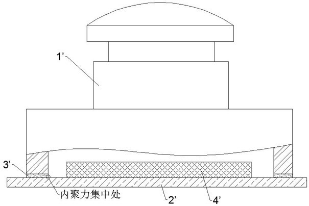
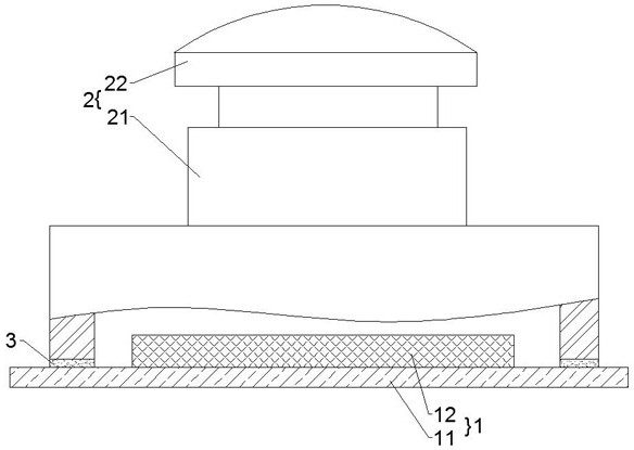
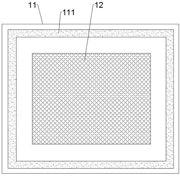
[0027] Such as Figure 2-4 As shown, a camera module includes a sensor assembly 1 and a lens assembly 2. The sensor assembly 1 includes a circuit board 11 and an image sensor 12 mounted on the central area of ​​the circuit board 11. The lens assembly 2 includes a base 21 and an optical lens 22 mounted in the base 21; the circuit board 11 has a first bonding area 111 on the periphery of the central area, and the bottom surface of the base 21 has a first bonding area 111; The second adhesive area 211 corresponding to the area 111, the first adhesive area 111 of the circuit board 11 and the second adhesive area 211 of the base 21 are fixed together by adhesive 3; the first adhesive The surface energy of the bonding area 111 or the second bonding area 211 increases from the inner edge to the outer edge.

[0028] Surface energy refers to the measure of the breaking of chemical bonds between molecules to create the surface of matter. The higher the surface energy of a substance, t...

Embodiment 2

[0034] Such as Figure 5 As shown, an assembly method of a camera module includes:

[0035] Step 1: If Figure 2-4 As shown, a sensor assembly 1 and a lens assembly 2 are provided. The sensor assembly 1 includes a circuit board 11 and an image sensor 12 mounted on the central area of ​​the circuit board 11. The lens assembly 2 includes a base 21 and a The optical lens 22 in the base 21; the periphery of the central area of ​​the circuit board 11 has a first bonding area 111, and the bottom surface of the base 21 has a second bonding area 111 corresponding to the first bonding area 111; The bonding area 211, the surface energy of the first bonding area 111 or the second bonding area 211 increases gradually from the inner edge to the outer edge;

[0036] Step 2: bonding and fixing the first bonding area 111 of the circuit board 11 and the second bonding area 211 of the base 21 together through glue 3 .

[0037] Among them, before step 1, it also includes:

[0038] The first ...


PUM


Abstract

The invention discloses a camera module, which comprises a sensor assembly with a circuit board and a lens assembly with a base, the circuit board has a first bonding area on the periphery of the central area, and the bottom surface of the base has a The second bonding area corresponding to the first bonding area, the first bonding area of ​​the circuit board and the second bonding area of ​​the base are fixed together by adhesive bonding; the first bonding area Or the surface energy of the second bonding area increases from the inner edge to the outer edge. The camera module can reduce poor appearance and improve focus accuracy and anti-shake accuracy. The invention also discloses an assembly method of the camera module.

Description

technical field [0001] The invention relates to camera technology, in particular to a camera module and an assembly method thereof. Background technique [0002] Such as figure 1 As shown, in the cameras used in consumer electronic products such as mobile phones, the lens assembly 1' and the circuit board 2' are generally bonded and fixed by adhesive 3', and the adhesive 3' will generate cohesive force when it is cured. The cohesive force is concentrated on the inner and outer edges of the bonding area between the lens assembly 1' and the circuit board 2', wherein the cohesive force concentrated on the inner edge of the bonding area will cause deformation of the central area of ​​the circuit board 2', that is, it will be mounted on the circuit board 2'. The image sensor 4' on the central area of ​​the board 2' will shift in position. If the circuit board 2' uses a flexible board (FPC), the deformation and position shifting will be serious and visible to the naked eye, which...

Claims


Application Information

Patent Timeline
Patent Type & Authority Patents(China)
IPC IPC(8): H04N5/225
CPCH04N23/50H04N23/57H04N23/55H04N23/54
Inventor 梁晓龙李保纲
Owner TRULY OPTO ELECTRONICS
Why Eureka
Try Eureka