

Surface lighting device
A lighting device and surface technology, which is applied to lighting devices, lighting device parts, lighting and heating equipment, etc., can solve the problems of the part of the frame becoming larger, it is difficult to meet the requirements of narrow frame, etc., to achieve design and manufacturing. Simplified effect
- Summary
- Abstract
- Description
- Claims
- Application Information
AI Technical Summary
Problems solved by technology
Method used
Image

Examples
no. 1 approach
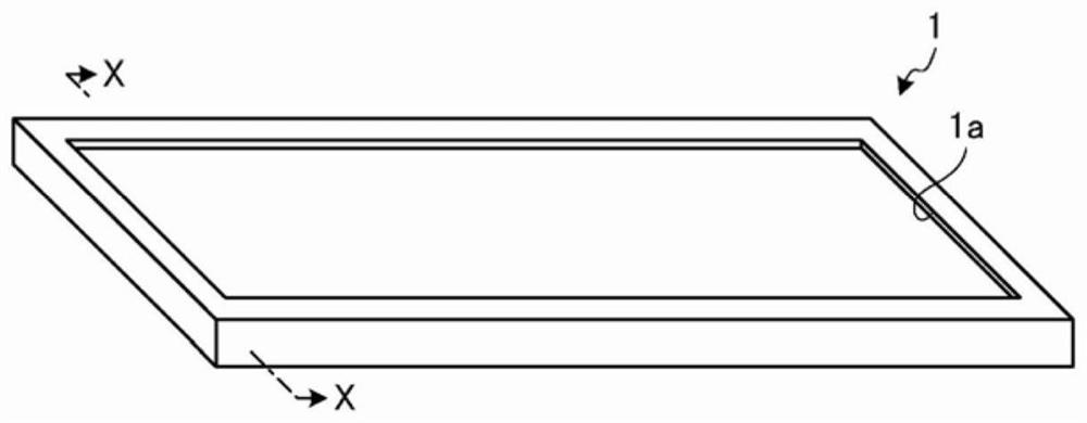
[0028] figure 1 It is an external perspective view of the backlight 1 according to the first embodiment. In addition, the backlight 1 is an example of a planar lighting device, and is provided on the back of a liquid crystal display device in a navigation device, an indicator, and the like.
[0029] exist figure 1 Among them, the backlight 1 has a rectangular and plate-like outer shape, has an opening 1 a on one surface (the upper surface in the figure), and irradiates light from the inside toward the outside. When used for a navigation device, a pointer, etc., the liquid crystal display device is attached to the surface provided with the opening 1a.
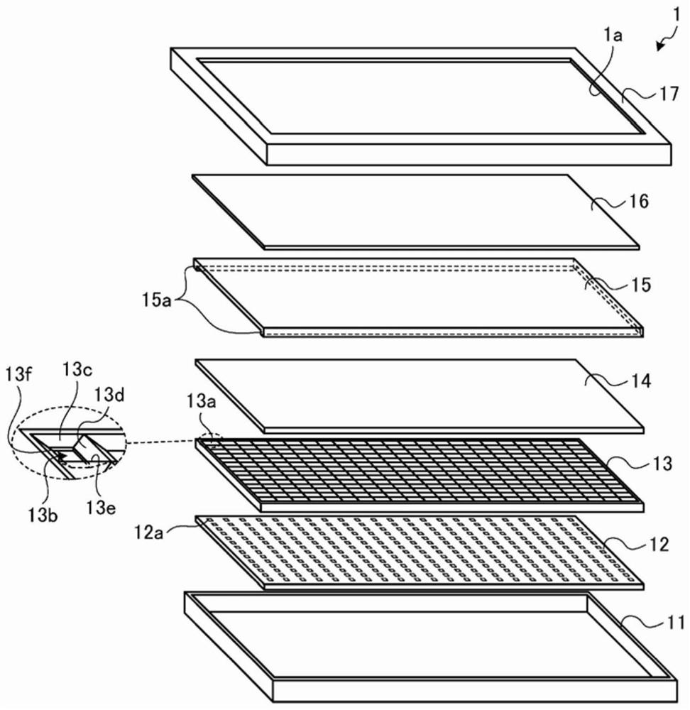
[0030] figure 2 yes figure 1 An exploded perspective view of the backlight 1 shown. exist figure 2 Among them, the backlight 1 includes a first frame 11 , an LED substrate 12 , a grid reflector 13 , a lens 14 , a diffuser 15 , a sheet 16 , and a second frame 17 .
[0031] The first frame 11 is formed in a box shape with...
no. 2 approach
[0049] In the first embodiment described above, the diffuser 15 is provided with a protruding portion that functions as a spacer. The second embodiment shows a case where a protrusion functioning as a spacer is provided on the lens 14 .
[0050] The appearance of the backlight 1 according to the second embodiment and figure 1 The backlight shown is the same, and the backlight 1 has a rectangular and plate-like outer shape, and has an opening 1a on one surface (the upper surface in the figure) to irradiate light from the inside toward the outside. A liquid crystal display device in a navigation device, a pointer, etc. is attached to the surface provided with the opening 1a.
[0051] Figure 5 It is an exploded perspective view of the backlight 1 according to the second embodiment. exist Figure 5 Among them, the backlight 1 includes a first frame 11 , an LED substrate 12 , a grid reflector 13 , a lens 14 , a diffuser 15 , a sheet 16 , and a second frame 17 .
[0052] The f...
no. 3 approach
[0065] Here, the case where the protruding portion is provided on the lens 14 side will be described more specifically. Figure 7 is a cross-sectional view of the backlight 1 according to the third embodiment, and Figure 6 likewise shows figure 1 Part of the X-X section view in. exist Figure 7 in, with Figure 6 Differently, one or more rod-shaped protrusions 14 b are provided on the surface of the lens 14 on the side of the diffuser 15 . Prism processing is performed on the surface of the lens 14 opposite to the diffuser 15 . In addition, processing for diffusing light, such as a laser spot, is performed on the surface of the lens 14 on the side of the diffuser 15 .
[0066] In addition, in Figure 7 Although the spacer 18 supporting the end of the diffuser 15 is provided separately from the lens 14 and the diffuser 15 , the lens 14 or the diffuser 15 and the spacer 18 may be integrally formed. in addition. Although not essentially different, one end of the cover pl...
PUM
 Abstract
Description
Claims
Application Information