Novel shock-proof wheelchair and using method thereof

A shock-absorbing and wheelchair technology, which is applied to patient chairs or special transportation tools, vehicle rescue, medical transportation, etc. , the effect of reducing wear

Inactive Publication Date: 2021-04-06
张言京
View PDF0 Cites 0 Cited by
  • Summary
  • Abstract
  • Description
  • Claims
  • Application Information

AI Technical Summary

Problems solved by technology

[0004] The purpose of the present invention is to solve the problem that the existing device will cause serious wear and tear on the user's hand and the shock absorption effect of the existing device is not good, and propose a new type of shock-absorbing wheelchair and its use method

Method used


Image

  • Novel shock-proof wheelchair and using method thereof
  • Novel shock-proof wheelchair and using method thereof
  • Novel shock-proof wheelchair and using method thereof

Examples


Embodiment 1

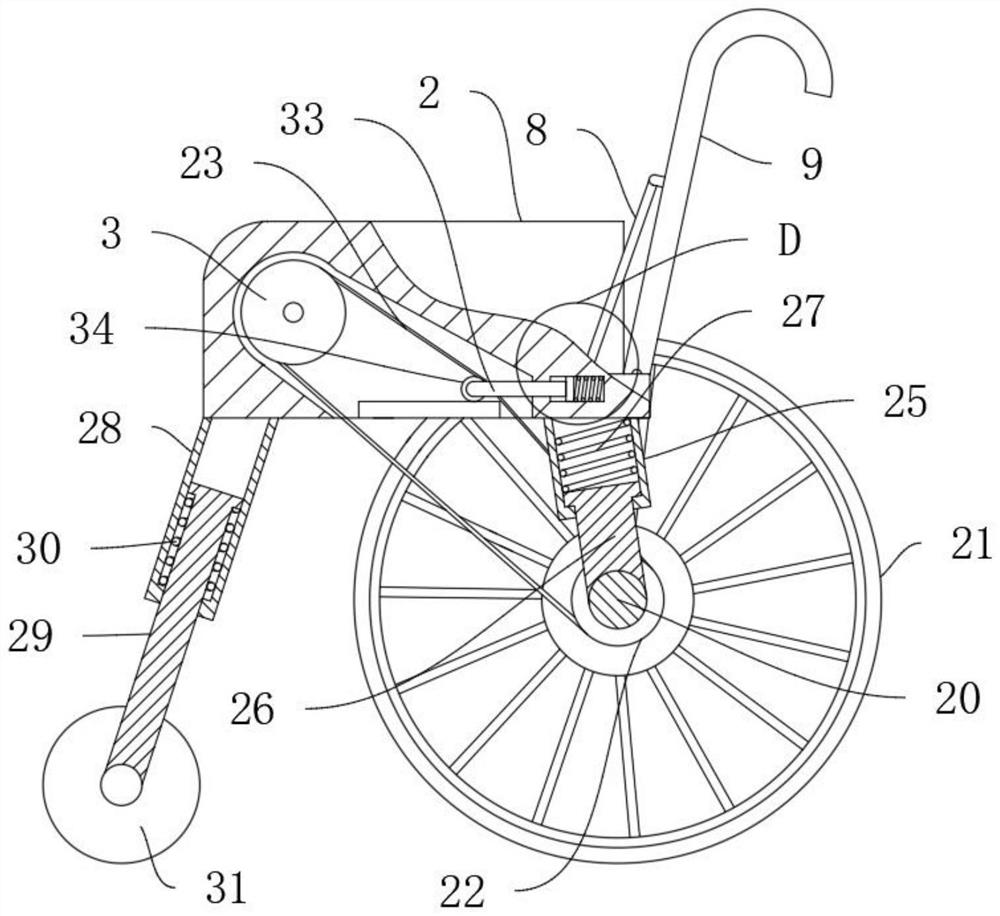
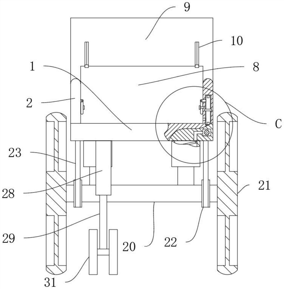
[0042] refer to Figure 1-8 , a new type of shock-absorbing wheelchair, comprising a base 1, the lower end of the base 1 is connected with a rotating main shaft 20, both ends of the rotating main shaft 20 are fixedly connected with a main rotating wheel 21, the upper end of the base 1 is symmetrically fixedly connected with a guard plate 2, and the upper end of the base 1 is a The side rotation is connected with a backrest 9, the backrest 9 and the guard plate 2 are perpendicular to each other, the side of the lower end of the base 1 close to the backrest 9 is symmetrically and fixedly connected with a first sliding cylinder 25, and the first sliding cylinder 25 is slidingly connected with a first sliding rod 26, One end of the first slide bar 26 away from the first slide cylinder 25 is rotationally connected with the rotating main shaft 20, and the first slide cylinder 25 is provided with a first spring 27, and the two ends of the first spring 27 are respectively connected wit...

Embodiment 2

[0047] refer to Figure 1-2 , a new type of shock-absorbing wheelchair, which is basically the same as Embodiment 1, furthermore: the two sides of the rotating main shaft 20 are fixedly connected with a driven pulley 22, and the guard plate 2 is rotatably connected with a driving pulley 3, and the driving pulley 3 A transmission belt 23 is connected to the top, and the end of the transmission belt 23 away from the driving pulley 3 is connected with the driven pulley 22, so as to be convenient to transmit the rotation.

Embodiment 3

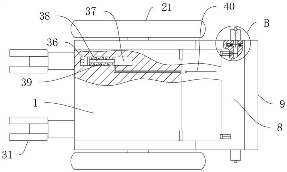
[0049] refer to Figure 1-2 , Figure 7 , a new type of shock-absorbing wheelchair, which is basically the same as Embodiment 1, furthermore: the driving pulley 3 is fixedly connected with a fixed block 4, and the guard plate 2 is provided with a circular chute 7, and the circular chute 7 is connected to the The fixed block 4 is matched, the fixed block 4 is rotatably connected with the first rotating rod 5, the first rotating rod 5 is slidably connected with the rectangular pin 6, and the guard plate 2 is provided with a rectangular groove matched with the rectangular pin 6, which is convenient to use The driving pulley 3 rotates.


PUM


Abstract

The invention discloses a novel shock-proof wheelchair and a using method thereof, and belongs to the technical field of shock-proof wheelchairs. The novel shock-proof wheelchair comprises a base, a rotating main shaft is connected to the lower end of the base, main rotating wheels are fixedly connected to the two ends of the rotating main shaft, protective plates are symmetrically and fixedly connected to the upper end of the base, a backrest is rotatably connected to one side of the upper end of the base, and the backrest is perpendicular to the protective plates. First sliding cylinders are symmetrically and fixedly connected to the side, close to the backrest, of the lower end of the base, and first sliding rods are slidably connected into the first sliding cylinders. According to the device, through a driving belt wheel, a first rotating rod, a transmission belt, a driven belt wheel, a rotating main shaft and a main rotating wheel, force is conveniently applied, abrasion to the hand of a user is reduced, through the first sliding barrel, the first sliding rod, the second sliding barrel and the second sliding rod, shock absorption of the device is achieved, and a patient can use the device more comfortably.

Description

technical field [0001] The invention relates to the technical field of shock-absorbing wheelchairs, in particular to a novel shock-absorbing wheelchair and a use method thereof. Background technique [0002] The wheelchair is an important tool for rehabilitation. It is not only a means of transportation for the physically disabled, but more importantly, it enables them to perform physical exercises and participate in social activities with the help of wheelchairs. Ordinary wheelchairs generally consist of a wheelchair frame, wheels, brakes and four seats. Partial composition; [0003] When the existing wheelchair is walking and moving, it depends on the user to turn the wheel to move the wheelchair, and to brake is also to stop the wheel by hand. The long-term use of this method will cause serious wear and tear on the user's hand. And the shock-absorbing effect of existing wheelchair is not good, runs into uneven road surface, can cause very big bump to patient, is unfavora...

Claims


Application Information

Patent Timeline
Patent Type & Authority Applications(China)
IPC IPC(8): A61G5/02A61G5/10A61G5/12
CPCA61G5/023A61G5/025A61G5/101A61G5/1032A61G5/1035A61G5/1067A61G2203/723A61G5/1051A61G5/122
Inventor 张言京
Owner 张言京
Why Eureka
Try Eureka