
Auxiliary intubation robot device based on visual scanning technology

A scanning technology and robot technology, applied in the field of intubation-assisted robot devices, can solve the problems of disturbing the stable and orderly progress of intubation, increasing workload, positioning effect and poor stability, etc., and achieve efficient and safe automatic intubation operation, firm limit The effect of bit and fixed, small movement

Active Publication Date: 2021-04-06
THE FIRST AFFILIATED HOSPITAL OF MEDICAL COLLEGE OF XIAN JIAOTONG UNIV
View PDF9 Cites 1 Cited by
  • Summary
  • Abstract
  • Description
  • Claims
  • Application Information

AI Technical Summary

Problems solved by technology

[0004] 1. Before intubation, it is impossible to adjust the upward state of the patient's head, that is, the effective opening and exposure of the airway glottis. When the subsequent intubation, the patient's head and airway state cannot be optimal , thus greatly affecting the success rate of intubation
[0005] 2. It is impossible to limit and fix the patient's head. During the intubation process, the medical staff still needs to hold the patient's head and fix it. However, this method not only increases the extra workload, but also due to the large artificial randomness, the positioning effect is not good. The stability is also poor, and the synchronization with the device cannot be guaranteed, so it also interferes with the stable and orderly intubation
[0006] 3. The function of the visual laryngoscope cannot be well considered, which restricts the clinical use. At the same time, when the uvula in the patient's throat area is obstructed during the first intubation, which affects the exposure of the glottis, it is inconvenient to perform a second microscopic examination. control, which in turn brings great trouble to subsequent intubation

Method used


Image

  • Auxiliary intubation robot device based on visual scanning technology
  • Auxiliary intubation robot device based on visual scanning technology
  • Auxiliary intubation robot device based on visual scanning technology

Examples


Embodiment Construction

[0033]Hereinafter, a variety of specific details are set forth in order to provide a thorough understanding of the concepts of the above-described embodiments, however, those skilled in the art will apparently described embodiments may be in these specific details. Some or all of the cases are practiced, in other cases, there is no specific description of the well-known processing steps.

[0034]In the description of the invention, it is to be understood that the terms "upper", "lower", "front", "rear", "left", "right", "top", "bottom", "inside", " "The orientation or positional relationship of the indication is based on the orientation or positional relationship shown in the drawings, which is only to facilitate the description of the invention, rather than indicating or implying that the device or element must have a specific orientation. The orientation is constructed and operated, so it is not understood to limit the invention.

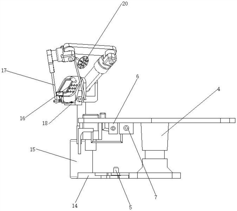
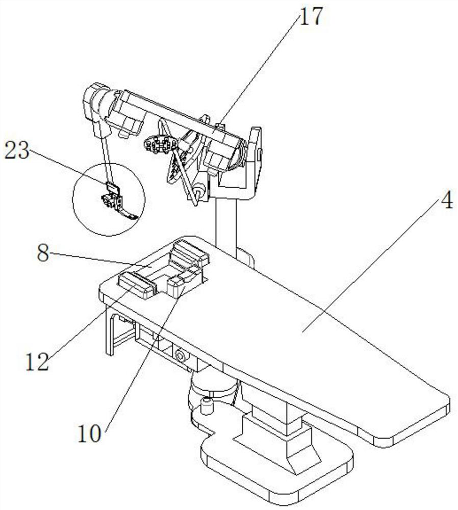
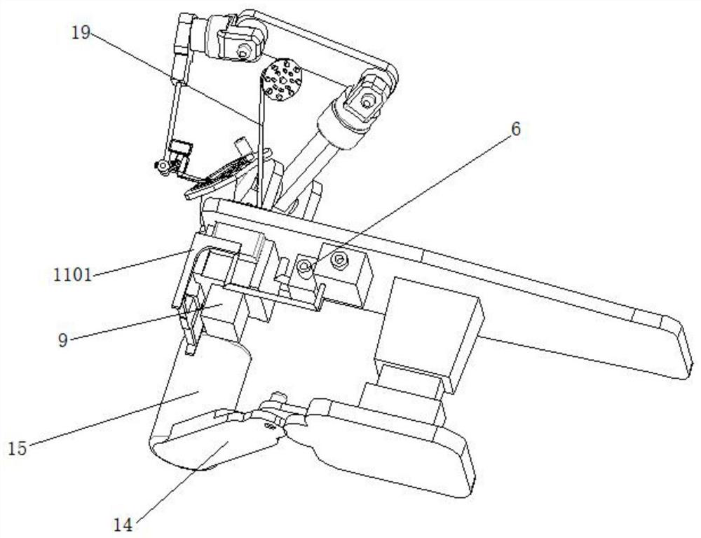
[0035]Such asfigure 1 ,figure 2 ,image 3 ,Figure 4 ,Fig...


PUM


Abstract

The invention discloses an auxiliary intubation robot device based on a visual scanning technology, and the device achieves the upward leaning of the head of a patient and the opening and exposure of an airway through the cooperation of head and neck posture regulation and control and a limiting and fixing mechanism, facilitates the subsequent intubation operation, and also limits and fixes the head of the patient. The problem that the head of a patient moves in the follow-up intubation process is avoided, safe and favorable conditions are provided for follow-up intubation, and efficient and safe automatic intubation operation is achieved on the basis of multi-axis movement of the robot arm in the visual scanning state through the design of a control table, the robot arm and a visual sensor in the robot arm assembly. finally, due to the adoption of a two-stage micro-control visual laryngoscope assembly, on the basis of one-time intubation positioning, accurate positioning of the tracheal catheter is achieved by means of a rotating structure, meanwhile, due to the fact that the movement amplitude in the whole process is small, harm to a patient is greatly avoided, and finally efficient, accurate and stable operation is guaranteed.

Description

Technical field[0001]The present invention relates to the field of intubation robots, in particular, to a auxiliary intubation robot device based on visual scanning techniques.Background technique[0002]The tracheal intubation is the primary step in emergency and general hemp surgery, which is significant in modern medicine. my country has more than 50,000 medical surgery a year. It takes more than 70,000 anesthetic doctors to complete over-intubation tasks, and with the increasing number of medical services and surgical volume, my country's narcotics is getting depleted. Highlight. At the same time, the tracheal intubation data shows that even in conventional non-emergency states, the success rate of the first tracheal intubation is 70%, the second intubation success rate is 89%, and the sustained hand is required. assist. In some emergency and special circumstances, there is also a cross-infection, exposure risk, such as patients with new coronavirus pneumonia, SARS, etc., patients...

Claims


Application Information

Patent Timeline
Patent Type & Authority Applications(China)
IPC IPC(8): A61M16/04A61M25/01A61B90/14A61B34/30A61B34/20
CPCA61M16/04A61M16/0488A61M25/0116A61B34/30A61B90/14A61B2034/301A61B2034/2065
Inventor 李锋梁晶
Owner THE FIRST AFFILIATED HOSPITAL OF MEDICAL COLLEGE OF XIAN JIAOTONG UNIV
Learn More