Interstage sealing ring sealing structure

A technology of sealing structure and sealing ring, applied in the direction of preventing leakage, stator, jet propulsion device, etc., can solve the difficulty of disassembling and assembling the spring pressing bolt of the middle face, and does not solve the problems of sealing, inconvenient installation and disassembly, etc. Improved maintainability, reduced risk of seal failure, and easy-to-achieve effects of seal structures

Active Publication Date: 2021-04-06
HANGZHOU TURBINE POWER GRP
View PDF8 Cites 0 Cited by
  • Summary
  • Abstract
  • Description
  • Claims
  • Application Information

AI Technical Summary

Problems solved by technology

The problem existing in the existing technical solutions is: in order to ensure the effectiveness of the seal, the spring needs to be compressed and loaded during installation. Since the force required to compress the spring is very large, and it can only be installed manually, it is very difficult to install and disassemble. Inconvenient, and when disassembling, the presence of pins at the horizontal mid-section of the stator blade seal ring will make it difficult to disassemble and assemble the mid-section spring compression bolts
[0006] The above published Chinese patents all relate to the field of industrial technology, among which patent CN111810248A solves the problems of cooling effect and aerodynamic efficiency; The opposite surface of the outlet part is provided with a circumferential groove part, and a sealing structure is arranged in the space formed by the groove part, and the solution is the circumferential sealing; none of the above-mentioned patents solves the axial and Radial sealing, and the structure is more complicated, the sealing effect is not good

Method used


Image

  • Interstage sealing ring sealing structure
  • Interstage sealing ring sealing structure
  • Interstage sealing ring sealing structure

Examples


Embodiment

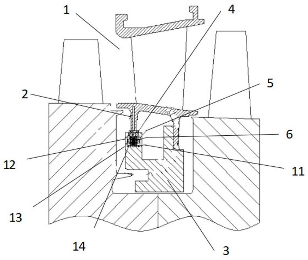
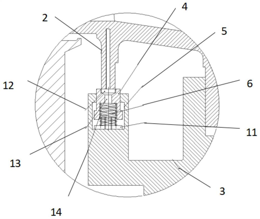
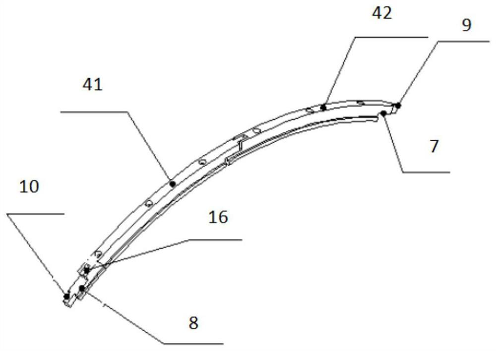
[0035] according to Figure 1-Figure 9The interstage sealing ring sealing structure shown includes the turbine stator blade 1, the sealing extension section 2 of the inner shroud of the stator blade, the interstage sealing ring 3, the T-shaped sealing ring body 4, the spring 6, and the T-shaped sealing ring. The sealing ring overlaps and seals the first extending section 7, the T-shaped sealing ring overlaps and seals the second extending section 8, the T-shaped sealing ring is embedded to seal the first extending section 9, and the T-shaped sealing ring is embedded to seal the second extending section 10. Gasket 11, T-shaped sealing ring guide hole 13; the T-shaped sealing ring body 4 includes a first T-shaped sealing ring 41 and a second T-shaped sealing ring 42; both ends of the T-shaped sealing ring body 4 Extending sections at both ends are provided, wherein, the end face of the first T-shaped sealing ring 41 is provided with a T-shaped sealing ring lapped to seal the sec...


PUM


Abstract

The invention relates to the technical field of industry, in particular to an interstage sealing ring sealing structure. The interstage sealing ring sealing structure comprises a turbine stationary blade, a sealing extending section of a stationary blade inner shroud ring, an interstage sealing ring, a T-shaped sealing ring body, a spring, a gasket and a T-shaped sealing ring guide hole. The T-shaped sealing ring body comprises a first T-shaped sealing ring and a second T-shaped sealing ring. The end face of the first T-shaped sealing ring is provided with a T-shaped sealing ring lap joint sealing second extending section and a T-shaped sealing ring embedded sealing second extending section. The end face of the second T-shaped sealing ring is provided with a T-shaped sealing ring lap joint sealing first extending section and a T-shaped sealing ring embedded sealing first extending section. An embedding groove, a spring mounting hole, the T-shaped sealing ring guide hole and a threaded hole are further formed in the T-shaped sealing ring body; and the spring is mounted in the spring mounting hole, and the gasket is mounted on the end part of the spring. The interstage sealing ring is simple in sealing structure, easy to implement and convenient to disassemble and assemble, the maintainability of a unit is improved, the cost is saved, and the sealing performance is good.

Description

technical field [0001] The invention relates to the field of industrial technology, in particular to an interstage sealing ring sealing structure. Background technique [0002] In industrial gas turbines, the operating temperature of the rotor disk is relatively high. If the temperature is not controlled, the excessively high temperature will lead to a decrease in strength, which will affect the safe operation of the unit. The usual method is to introduce cooling air to cool the wheel disc. The cooling air is generally supplied from the air supply cavity at the outer periphery of the stator vane. After the gas flows through the inner channel of the stator vane, it enters the inner shroud of the stator vane and the interstage seal. The air supply chamber composed of the ring, finally cools the upstream and downstream discs respectively through the upper and downstream sealing teeth, and seals the dynamic and static gaps to prevent high-temperature gas from invading the disc c...

Claims


Application Information

Patent Timeline
Patent Type & Authority Applications(China)
IPC IPC(8): F02C7/28F01D9/02F01D11/00
CPCF01D9/02F01D11/003F02C7/28
Inventor 张发生蓝吉兵隋永枫潘慧斌邵艳红马思亮俞胤杰戴斌张伟赵鸿琛赵旭洋
Owner HANGZHOU TURBINE POWER GRP
Why Eureka
Try Eureka