Supercharge Your Innovation With Domain-Expert AI Agents!

Vacuumizing control device

A control device and vacuuming technology, applied in pump control, liquid variable capacity machinery, machine/engine, etc., can solve the problems of energy waste and shorten the service life of vacuum pump equipment parts and so on.

Pending Publication Date: 2021-04-06
昆山书豪仪器科技有限公司
View PDF0 Cites 0 Cited by
  • Summary
  • Abstract
  • Description
  • Claims
  • Application Information

AI Technical Summary

Problems solved by technology

[0004] Therefore, the technical problem to be solved by the present invention is to overcome the defects of energy waste caused by the continuous operation of the vacuum pump in the prior art and shorten the service life of the parts of the vacuum pump equipment, thereby providing a vacuum control device

Method used


Image

  • Vacuumizing control device
  • Vacuumizing control device
  • Vacuumizing control device

Examples


Embodiment Construction

[0025] The technical solutions of the present invention will be clearly and completely described below in conjunction with the accompanying drawings. Apparently, the described embodiments are some of the embodiments of the present invention, but not all of them. Based on the embodiments of the present invention, all other embodiments obtained by persons of ordinary skill in the art without making creative efforts belong to the protection scope of the present invention.

[0026] In the description of the present invention, it should be noted that the terms "first", "second", and "third" are used for description purposes only, and should not be understood as indicating or implying relative importance.

[0027]In the description of the present invention, it should be noted that unless otherwise specified and limited, the terms "installation", "connection" and "connection" should be understood in a broad sense, for example, it can be a fixed connection or a detachable connection. ...


PUM


Abstract

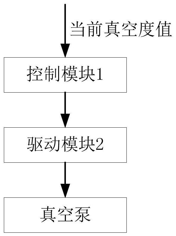
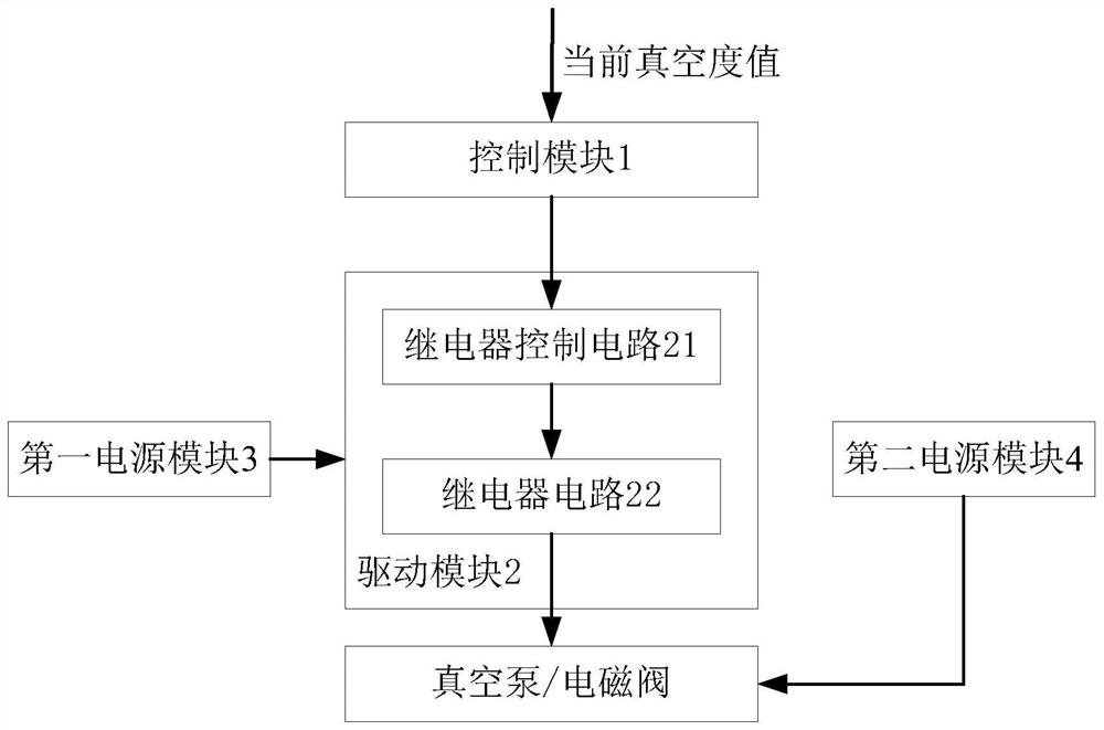
The vacuumizing control device provided by the invention comprises a control module and a driving module. The control module is used for receiving the current vacuum degree value of a target vacuumizing chamber and generating a logic control signal according to the current vacuum degree value and a preset vacuum degree threshold value. The input end of the driving module is connected with the control module, and the output end of the driving module is connected with a vacuum pump for receiving the logic control signal and generating a driving signal according to the logic control signal so as to drive the vacuum pump to vacuumize. Through the implementation of the invention, when the current vacuum degree value is not within the preset vacuum degree threshold range, the vacuum pump is driven to vacuumize, and when the current vacuum degree value is within the preset vacuum degree threshold range, the vacuum pump is stopped from vacuumizing, so that the continuous operation time of the empty pump is shortened, and the service life of equipment parts is prolonged.

Description

technical field [0001] The invention relates to the field of vacuum control, in particular to a vacuum control device. Background technique [0002] Both atomic emission spectrometry and atomic emission spectrometer quantitative analysis require an optical path spectroscopic imaging system to perform spectroscopic and full-spectrum data collection on the excitation light source. In order to eliminate the external interference brought by external light, air and mechanical deformation to the optical path spectroscopic imaging system, the optical chamber in the optical path spectroscopic imaging system needs to be in a sealed constant temperature vacuum state. Specifically, on the one hand, changes in the temperature and vacuum inside the optical chamber will cause the intensity of the excitation light source in the optical chamber to be unstable, and the longer the wavelength of the analytical light, the better the air absorption effect, resulting in a decrease in the intensit...

Claims


Application Information

Patent Timeline
IPC IPC(8): F04B49/06F04B37/14
CPCF04B37/14F04B49/06
Inventor 徐荣网李玉泉刘少龙耿建峰
Owner 昆山书豪仪器科技有限公司
Features
  • R&D
  • Intellectual Property
  • Life Sciences
  • Materials
  • Tech Scout
  • Unparalleled Data Quality
  • Higher Quality Content
  • 60% Fewer Hallucinations
Learn More