Plate connecting method
A technology of panel connection and connectors, which is applied in the field of furniture manufacturing, can solve the problems of high difficulty, low furniture assembly efficiency, cumbersome installation and use of panel connectors, etc., and achieve the effect of convenient connection and improved efficiency
- Summary
- Abstract
- Description
- Claims
- Application Information
AI Technical Summary
Problems solved by technology
Method used
Image

Examples
Embodiment 1
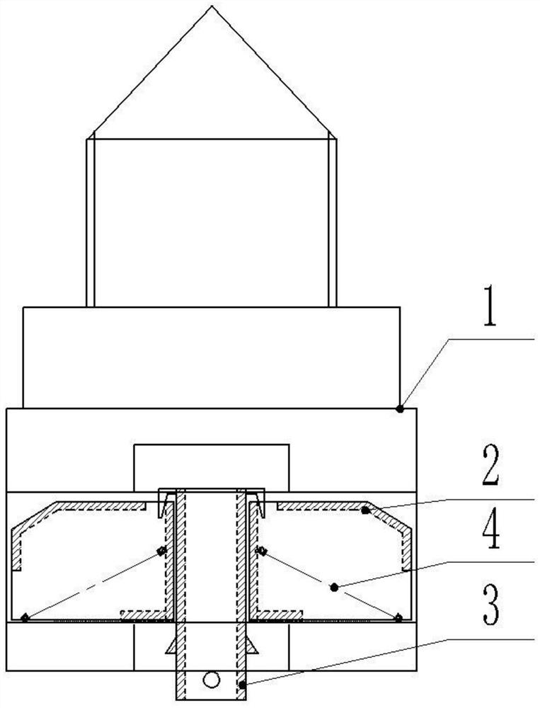
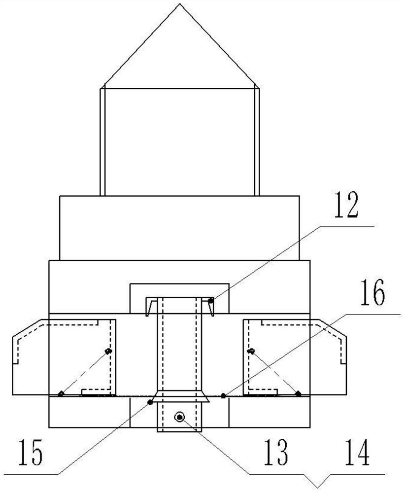
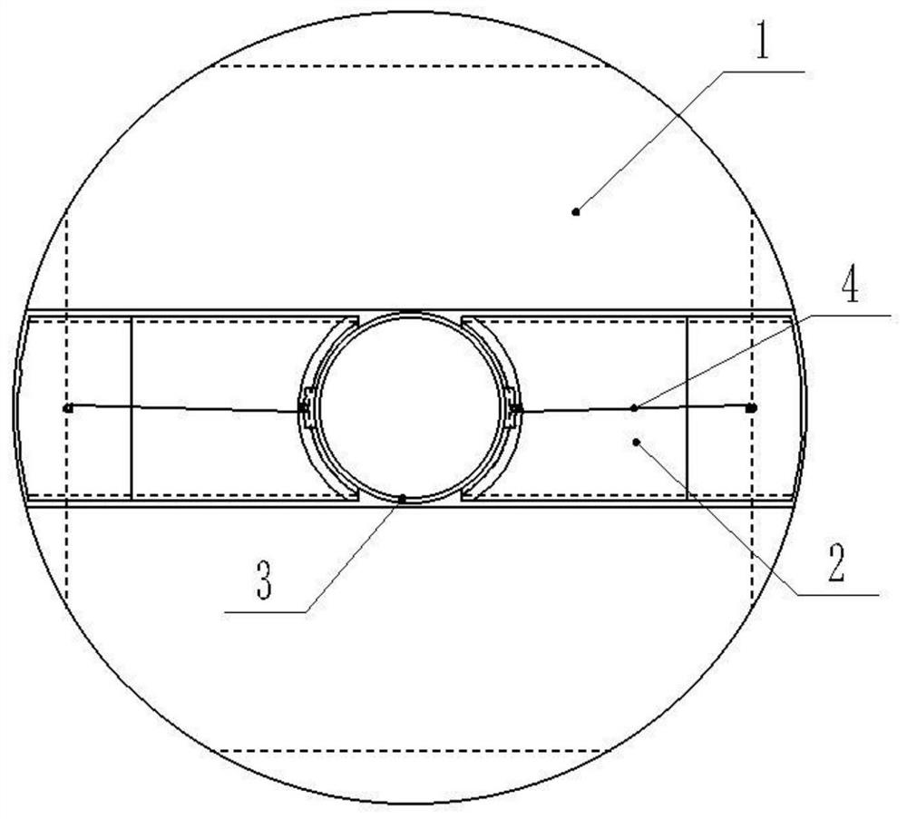
[0052] Such as Figure 1-8 As shown, a method for connecting plates of the present invention comprises the steps of:
[0053] Step 1, setting up the connecting piece includes a plug connecting body 1, a telescopic stopper 2, a locking rod 3 and a telescopic extension spring 4, one end of the plug connecting body 1 is provided with a stud screw 5, and the other end of the plug connecting body 1 is provided with a connecting plug rod 6. The rod body at the bottom end of the connecting plug rod 6 is radially provided with a telescopic through hole 7, and the bottom end of the connecting plug rod 6 is axially provided with a locking rod blind hole 8, and the telescopic through hole 7 is connected with the locking rod blind hole. 8 cross;
[0054] The two ends of the telescopic through hole 7 are respectively inserted with a telescopic stopper 2, the telescopic stopper 2 is a cavity structure, the inner end of the telescopic stopper 2 is provided with a concave arc plate 21, and t...
Embodiment 2
[0071] Such as Figure 1-8 As shown, a method for connecting plates of the present invention, on the basis of Embodiment 1, the inverted T-shaped drilling 19 drilling method includes steps:
[0072] Step 1, setting the drill tube body 22 includes an upper drill tube 26, a lower drill tube 27 and a drill tube connecting plate 28, the upper drill tube 26 and the lower drill tube 27 are connected by the drill tube connecting plate 28, and the upper end of the upper drill tube 26 is set There is a drill shank body 44, the middle part of the lower end of the drill shank body 44 is provided with an adjustment groove 29, and the inner axis position of the lower drill barrel 27 is provided with a guide connecting wire shaft 30 connected with the drill barrel connecting plate 28, and at the bottom of the lower drill barrel 27 The head is provided with a drill bit block 24, and the drill bit block 24 is connected on the guide connecting wire shaft 30 through a bearing;
[0073] Step 2....
PUM
 Abstract
Description
Claims
Application Information
PatSnap Eureka turns technology decisions into work you can execute. Powered by our Innovation Knowledge Graph, it runs expert workflows across engineering, life sciences, materials and intellectual property. Get your review-ready output in minutes.


