Damping device capable of automatically adjusting damping stroke according to vibration intensity

An automatic adjustment and shock absorber technology, applied in the direction of shock absorbers, springs/shock absorbers, shock absorbers, etc., can solve the problems of small shock absorbing spring deformation, poor shock absorbing effect, spring deformation, etc., to avoid The effect of excessive deformation and changing sensitivity

Inactive Publication Date: 2021-04-06
深圳市佳键合科技有限公司
View PDF7 Cites 1 Cited by
  • Summary
  • Abstract
  • Description
  • Claims
  • Application Information

AI Technical Summary

Problems solved by technology

[0002] The shock absorber mainly uses the deformation of the spring to absorb the impact force suddenly acting on the shock absorber column, thereby reducing the impact force transmitted by the shock absorber. The shock absorber stroke of the current shock absorber is fixed, and the elastic force of the shock absorber spring is fixed. If the elastic force of the shock absorbing spring is too large, when a small impact force acts on the shock absorbing column, the deformation of the shock absorbing spring will be small, and the shock absorbing effect will be poor. If the spring force of the shock spring is too small, if a large impact force acts on the shock-absorbing column, the shock-absorbing spring will be over-compressed, which will easily lead to over-deformation of the spring and reduce its service life

Method used


Image

  • Damping device capable of automatically adjusting damping stroke according to vibration intensity
  • Damping device capable of automatically adjusting damping stroke according to vibration intensity
  • Damping device capable of automatically adjusting damping stroke according to vibration intensity

Examples


Embodiment Construction

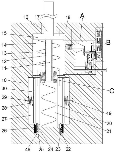
[0016] Combine below Figure 1-4 The present invention is described in detail, wherein, for the convenience of description, the orientations mentioned below are defined as follows: figure 1 The up, down, left, right, front and back directions of the projection relationship itself are the same.

[0017] A shock-absorbing device that can automatically adjust the shock-absorbing stroke according to the vibration intensity described in conjunction with accompanying drawings 1-4 includes a main box body 10, and a primary shock-absorbing cavity 14 is provided inside the main box body 10, and the primary shock-absorbing cavity The upper side of the shock chamber 14 is provided with a shock-absorbing column sliding chamber 16 with an upward opening, the lower side of the primary shock-absorbing chamber 14 is connected with a secondary shock-absorbing chamber 21, and the left and right sides of the secondary shock-absorbing chamber 21 are connected with a A left-right symmetrical magn...


PUM


Abstract

The invention relates to the related field of dampers, and discloses a damping device capable of automatically adjusting damping stroke according to vibration intensity. The damping device comprises a main box body, a primary damping cavity is arranged in the main box body, a damping column sliding cavity with an upward opening is arranged on the upper side of the primary damping cavity, a secondary damping cavity communicates with the lower side of the primary damping cavity, and the left side and the right side of the secondary damping cavity communicate with magnetic sliding plate cavities which are symmetrical left and right with the secondary damping cavity as the center. The elastic force borne by a damping column push plate can be automatically adjusted according to the pressure borne by a damping column and the downward moving speed of the damping column, and therefore when the pressure borne by the damping column is small, the enough long buffering stroke can be guaranteed; and accordingly it is guaranteed that the damping column can be sufficiently buffered; when the damping column bears large pressure, it can also be guaranteed that the downward moving distance of the damping column is not too large, and the situation that a primary damping spring is damaged due to too large deformation is avoided; and meanwhile, the sensitivity of damping stroke adjustment can be changed, and the device can meet the damping requirements in different operation environments.

Description

technical field [0001] The invention relates to the related field of shock absorbers, in particular to a shock absorber capable of automatically adjusting the shock absorbing stroke according to the vibration intensity. Background technique [0002] The shock absorber mainly uses the deformation of the spring to absorb the impact force suddenly acting on the shock absorber column, thereby reducing the impact force transmitted by the shock absorber. The shock absorber stroke of the current shock absorber is fixed, and the elastic force of the shock absorber spring is fixed. If the elastic force of the shock absorbing spring is too large, when a small impact force acts on the shock absorbing column, the deformation of the shock absorbing spring will be small, and the shock absorbing effect will be poor. If the spring force of the shock spring is too small, if a large impact force acts on the shock-absorbing column, the shock-absorbing spring will be over-compressed, which will...

Claims


Application Information

Patent Timeline
Patent Type & Authority Applications(China)
IPC IPC(8): F16F7/00F16F7/02F16F7/06F16F7/10F16F7/116
CPCF16F7/00F16F7/023F16F7/116F16F7/1028F16F7/06F16F2222/06F16F2222/04F16F2222/08F16F2238/026
Inventor 李建好
Owner 深圳市佳键合科技有限公司
Why Eureka
Try Eureka