Inductor component

A technology for inductors and components, applied in the field of inductor components, can solve problems such as easy temperature rise, and achieve the effect of suppressing the reduction of reliability

Active Publication Date: 2021-04-06
MURATA MFG CO LTD
View PDF6 Cites 0 Cited by
  • Summary
  • Abstract
  • Description
  • Claims
  • Application Information

AI Technical Summary

Problems solved by technology

[0012]Inductor wiring located between inductor wiring at both ends As mentioned above, temperature tends to rise

Method used


Image

  • Inductor component
  • Inductor component
  • Inductor component

Examples


no. 1 approach >

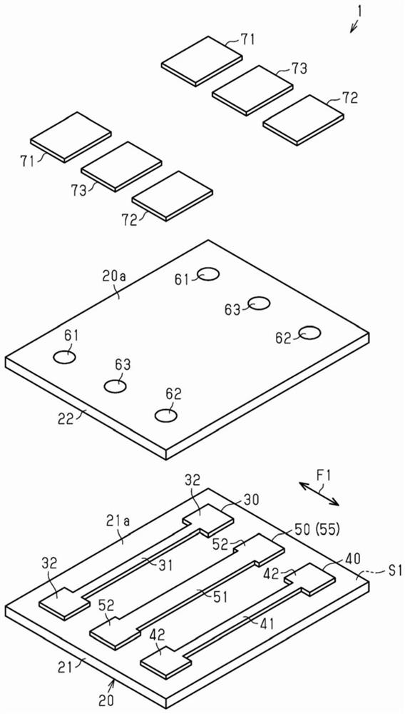
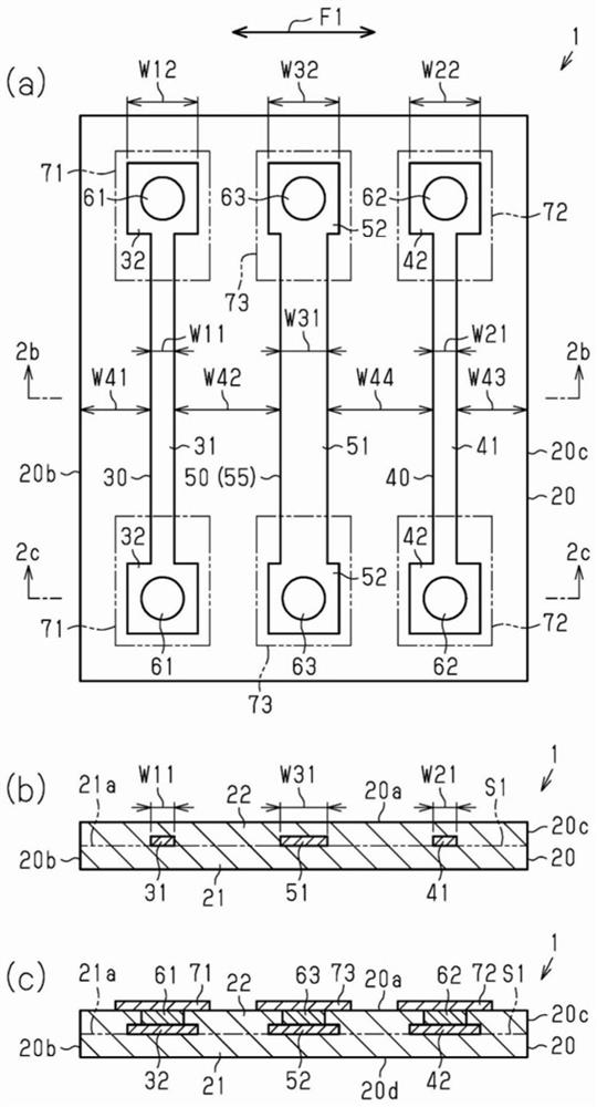
[0045] figure 1 The illustrated inductor component 1 is, for example, a surface-mount inductor component mounted in electronic equipment such as a personal computer, a DVD player, a digital camera, a television, a mobile phone, and an automotive electronic device.

[0046] Such as figure 1 As shown, the inductor component 1 includes a main body 20, a first inductor wiring 30 located inside the main body 20 and extending on the imaginary plane S1, and a first inductor wiring 30 located inside the main body 20 on the imaginary plane S1 (parallel to the imaginary plane S1). ) extended second inductor wiring 40 . In addition, the inductor component 1 includes a third inductor wiring extending on the imaginary plane S1 (parallel to the imaginary plane S1 ) between the first inductor wiring 30 and the second inductor wiring 40 inside the main body 20 . 50. In addition, the inductor component 1 includes vertical wirings 61 and 62 penetrating through the inside of the main body 20 ...

no. 2 approach >

[0095] Hereinafter, a second embodiment of the inductor component will be described.

[0096] In addition, in this embodiment, the same code|symbol is attached|subjected to the same code|symbol about the same component as the above-mentioned embodiment, or a component corresponding to the above-mentioned embodiment, and a part or all of the description is abbreviate|omitted.

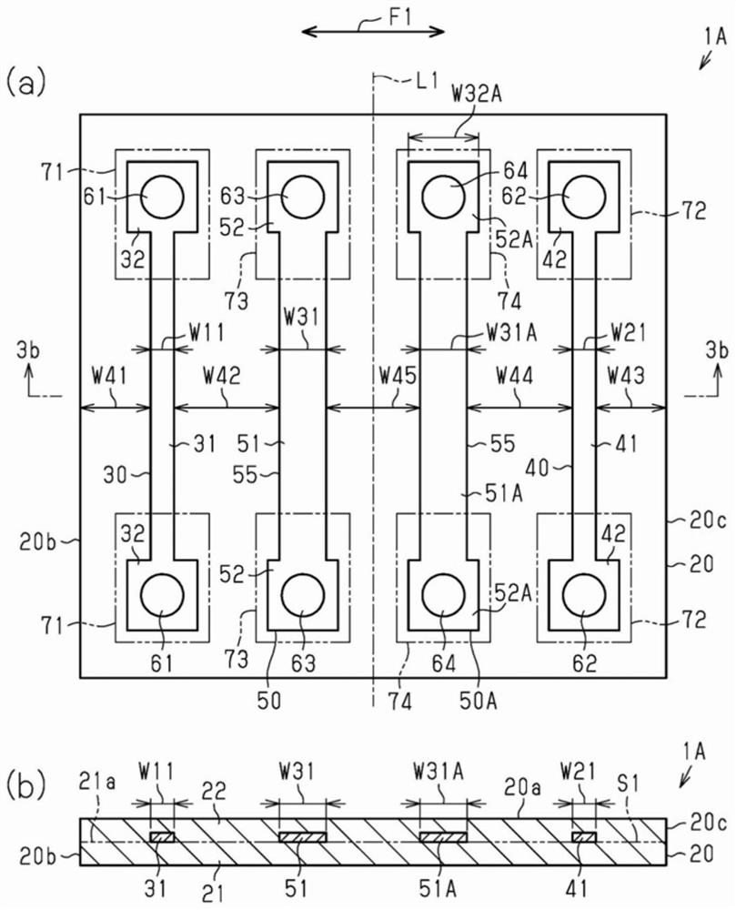
[0097] image 3 (a) and image 3 The inductor component 1A shown in (b) is the inductor component 1 of the above-mentioned first embodiment, further comprising: The structure of the fourth inductor wiring 50A extending parallel to the imaginary plane S1. The fourth inductor wiring 50A is a low-resistance inductor wiring 55 . That is, the inductor component 1A of the present embodiment differs from the inductor component 1 of the above-described first embodiment in the number of low-resistance inductor wiring lines 55 . The inductor component 1A has two low-resistance inductor wirings 55 between the f...


PUM


Abstract

The invention provides an inductor component capable of suppressing reliability reduction caused by heat. The inductor component includes a main body 20, a first inductor wiring 30 located inside the main body 20 and extending on a virtual plane S1, and a second inductor wiring 40 located inside the main body 20 and extending in parallel to the virtual plane S1. The inductor component includes a third inductor wiring 50 located between the first inductor wiring 30 and the second inductor wiring 40 inside the main body 20 and extending in parallel to the virtual plane S1. The inductor component includes vertical wirings 61-63 passing through the inside of the main body 20 from each of the first to third inductor wirings 30, 40, 50 to a surface of the main body 20 in a direction perpendicular to the virtual plane S1. The third inductor wiring 50 is a low-resistance inductor wiring 55 having a DC electrical resistance smaller than those of the first inductor wiring 30 and the second inductor wiring 40.

Description

technical field [0001] The present disclosure relates to inductor components. Background technique [0002] In an inductor component mounted on an electronic device, for example, as described in Patent Document 1, there is a structure that constitutes an inductor array including a main body and a magnetic material layer that is a sintered body of ferrite laminated. formed; and a plurality of inductor wirings located on the same virtual plane inside the main body. [0003] Patent Document 1: Japanese Patent Laid-Open No. 2002-110432 [0004] In the inductor component constituting the above-mentioned inductor array, generally, a plurality of inductor wirings are formed so that the wiring width and line length are the same, and the DC resistances are the same. Furthermore, when the inductor component includes three or more inductor wirings aligned on the same virtual plane, the inductor wirings located at both ends of the parallel arrangement direction of the inductor wirings...

Claims


Application Information

Patent Timeline
Patent Type & Authority Applications(China)
IPC IPC(8): H01F17/00H01F27/28
CPCH01F27/08H01F27/28H01F17/0013H01F2017/0066H01F27/292H01F2017/048H01F17/04H01F27/2823
Inventor 山内浩司吉冈由雅国森敬介
Owner MURATA MFG CO LTD
Why Eureka
Try Eureka