
Refrigeration device

A refrigeration device and refrigerant technology, applied in heating methods, lighting and heating equipment, indirect heat exchangers, etc., can solve problems such as performance degradation, achieve improved assembly, inhibit salt damage and electrical corrosion, and inhibit performance degradation. Effect

Pending Publication Date: 2019-10-25
DAIKIN IND LTD
View PDF6 Cites 0 Cited by
  • Summary
  • Abstract
  • Description
  • Claims
  • Application Information

AI Technical Summary

Problems solved by technology

Also, in the case where the air flows toward the header header side of the heat exchanger by bypassing without properly passing through the heat transfer portion (heat exchange portion) of the heat exchanger, since performance degradation occurs, it is necessary to suppress the bypass.

Method used


Image

  • Refrigeration device
  • Refrigeration device
  • Refrigeration device

Examples


example 22

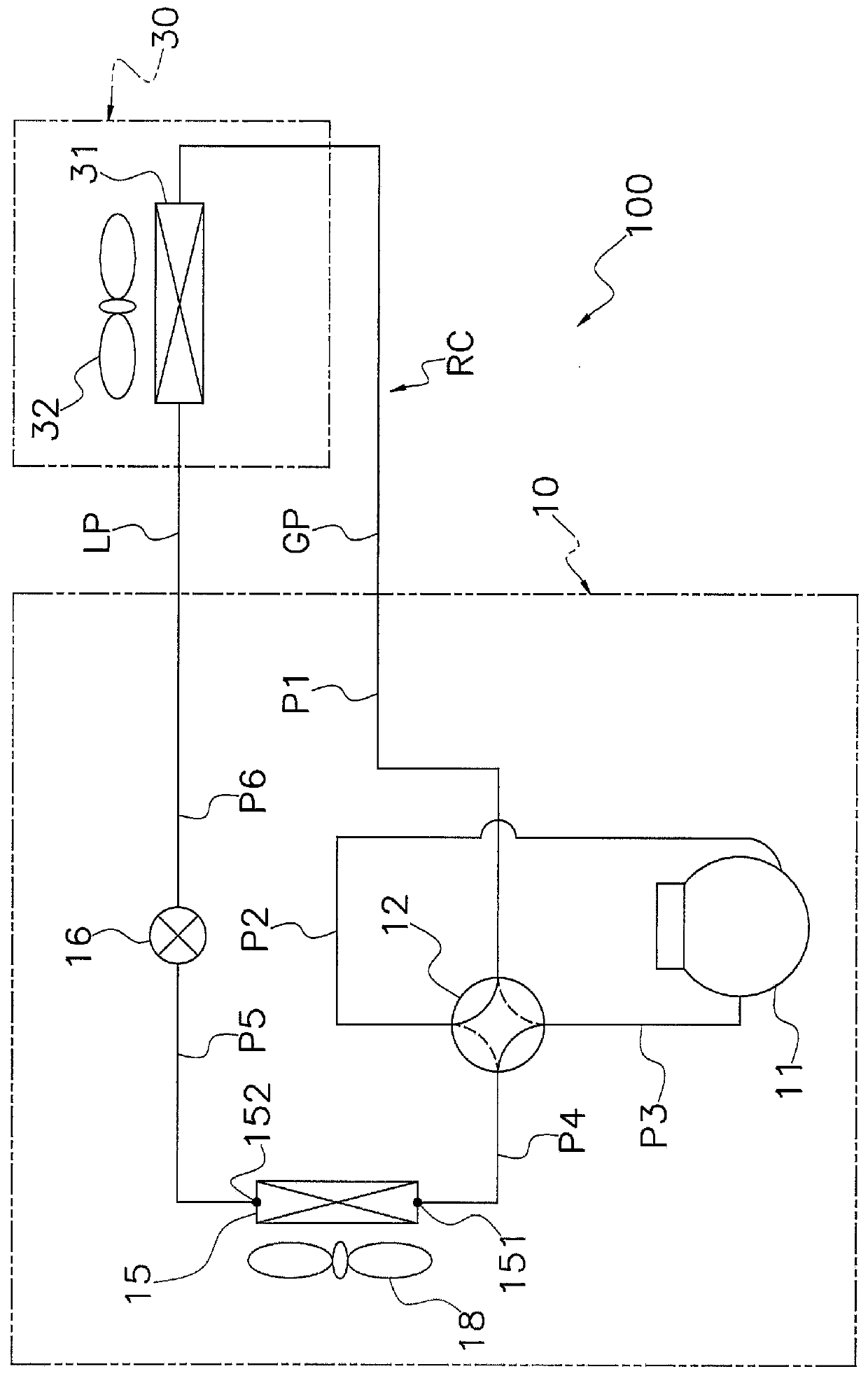
[0283] In the above-mentioned embodiment, the outdoor heat exchanger 15 has 12 heat transfer tubes 60 (60a-60l). However, the number of heat transfer tubes 60 included in the outdoor heat exchanger 15 can be appropriately changed according to design specifications and installation environments. For example, the outdoor heat exchanger 15 may have 11 or less or 13 or more heat transfer tubes 60 .

example 23

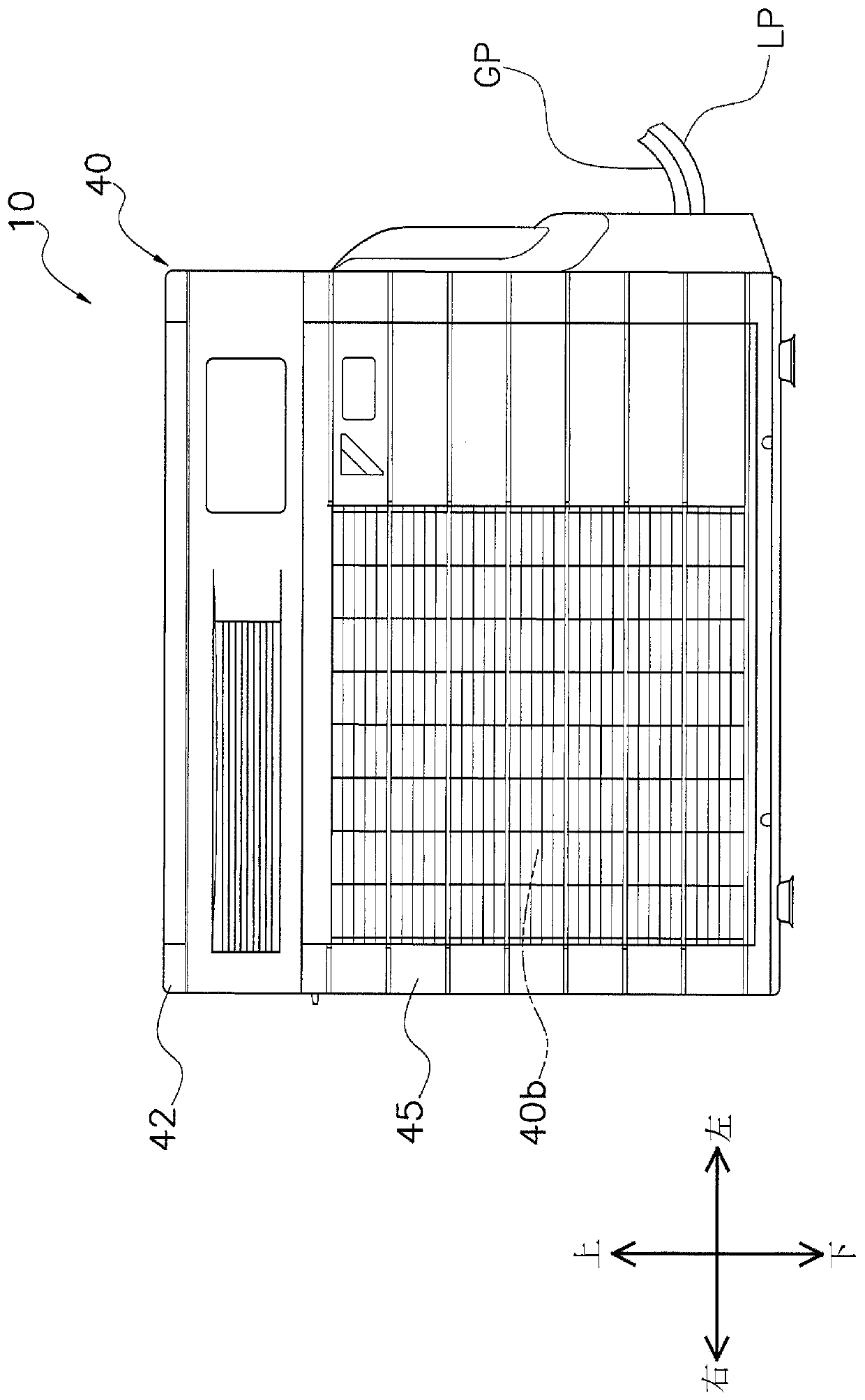
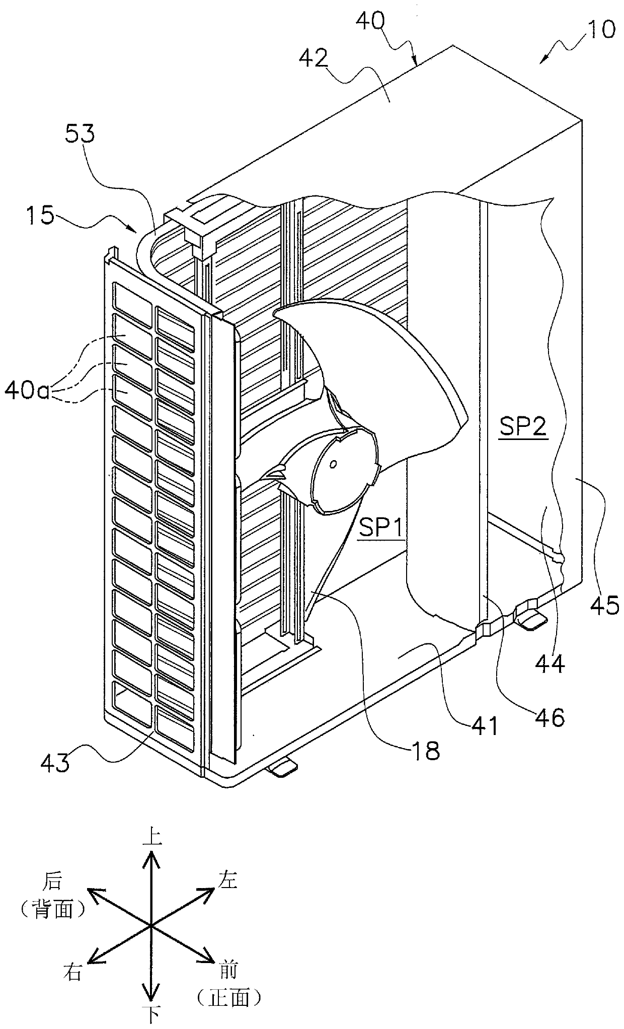
[0285] In the above-described embodiment, the outdoor unit 10 is of a so-called trunk type that takes in the flow of outdoor air AF from the rear side and the side surface and blows it out in the front direction. However, the outdoor unit is not necessarily limited thereto, and other types of outdoor units may also be used. For example, the outdoor unit 10 may be of a so-called upblown type in which an inlet for the outdoor air flow AF is formed on the side and an air outlet is formed on the top.

[0286] (8-24) Modification 24

[0287] The configuration of the refrigerant circuit RC in the above-described embodiment can be appropriately changed according to the installation environment and design specifications. Specifically, some circuit elements in the refrigerant circuit RC may be replaced with other devices, and may be appropriately omitted when not necessarily necessary. For example, the four-way switching valve 12 may be appropriately omitted. In addition, in the ref...

Deformed example 27

[0293] In the above-described embodiments, the present invention is applied to the outdoor unit 10 of the air-conditioning apparatus 100 as a refrigeration apparatus. However, the invention can also be applied to other refrigeration devices. For example, it is also possible that the present invention is applied to other refrigerating devices having a refrigerant circuit and a heat exchanger such as a low-temperature refrigerating device or a water supply device or a heat pump cooler used in a refrigerated / refrigerated container or a warehouse / showcase. device.

[0294] (8-28) Modification 28

[0295] The configuration of the outdoor unit 10 in the above-mentioned embodiment can be changed as appropriate. For example, the outdoor unit 10 can also be Figure 25 The illustrated outdoor unit 10A is constructed as shown. Next, the outdoor unit 10A will be described. In addition, description of the same parts as those of the outdoor unit 10 will be omitted.

[0296] Figure 2...


PUM


Abstract

This air conditioning device (100) is provided with a unit casing (40), an outdoor heat exchanger (15) contained within the unit casing (40), and a plate member (80). The unit casing (40) has formed therein a blower compartment (SP1) and a machine compartment (SP2). The outdoor heat exchanger (15) has: a heat exchange section (50) which includes a plurality of heat transfer pipes (60) through which a refrigerant flows, is disposed in the blower compartment (SP1), and exchanges heat between the refrigerant and an outdoor air flow (AF); and a header collecting pipe (70) connected to the heat transfer pipes (60) and disposed in the machine compartment (SP2). The header collecting pipe (70) includes a header body (75). The plate member (80) includes a front surface (811) for shielding the machine compartment (SP2) from the outdoor air flow (AF). The plate member (80) is affixed to the header collecting pipe (70) and is also affixed to the unit casing (40) or a partition plate (46) disposedin the unit casing (40).

Description

technical field [0001] The present invention relates to freezing devices. Background technique [0002] Conventionally, among refrigerating apparatuses, refrigerating apparatuses having a heat exchanger for exchanging heat between a refrigerant and an air flow have been widely used. In such a refrigeration device, it is necessary to take various countermeasures to suppress a decrease in reliability from the following point of view. For example, it is necessary to take countermeasures against salt damage when refrigeration equipment is installed in coastal areas. In addition, in order to cope with the connection of pipes and equipment of dissimilar metals (such as copper and aluminum / aluminum alloy) in the heat exchanger, it is also necessary to consider countermeasures against electric corrosion. Also, when the air flow bypasses toward the header header side of the heat exchanger without properly passing through the heat transfer portion (heat exchange portion) of the heat...

Claims


Application Information

Patent Timeline
Patent Type & Authority Applications(China)
IPC IPC(8): F24F1/16F24F13/30F28D1/053F28F9/00
CPCF24F1/16F28D1/053F28F9/00F24F1/56F28D1/05391F28D2021/0068F28F9/02F28F2215/12F28F2250/06F28F2275/04
Inventor 久保博治中野宽之笹井泰弘
Owner DAIKIN IND LTD
Learn More