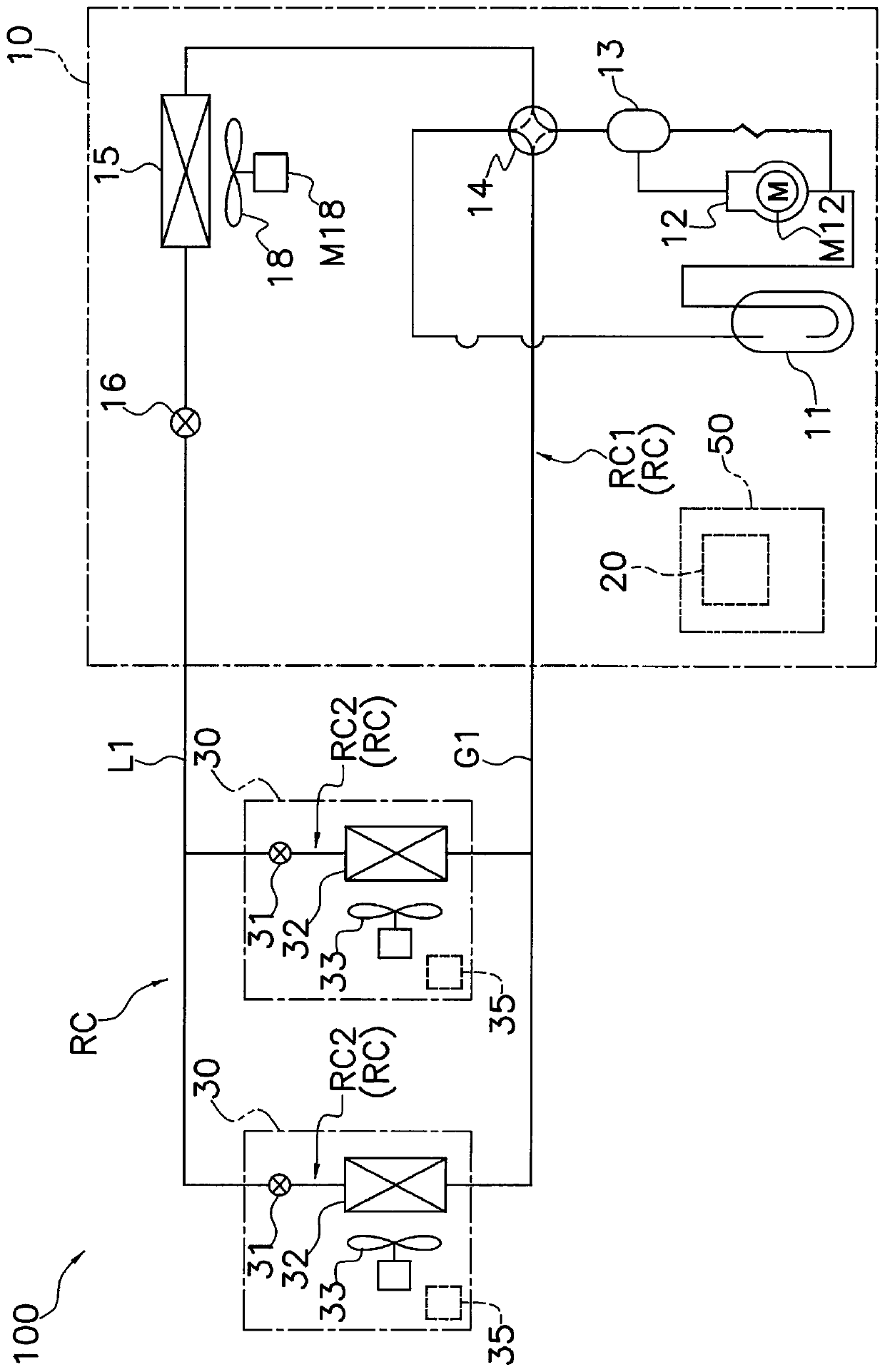
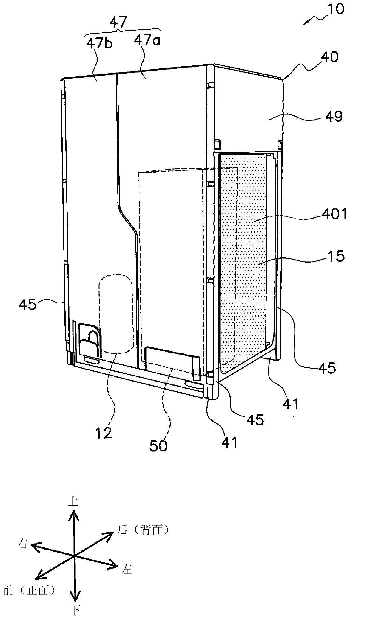
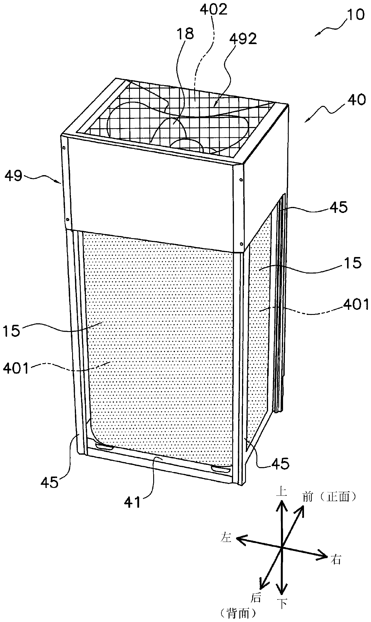
Outdoor unit for refrigeration device
A technology for outdoor units and refrigerators, used in electrical components, cooling/ventilation/heating renovation, heating methods, etc., can solve the problems of insufficient cooling performance and insufficient cooling of heat-generating components, and achieves the reduction of cooling capacity, The effect of suppressing the decrease in cooling performance and large cooling capacity
- Summary
- Abstract
- Description
- Claims
- Application Information
AI Technical Summary
Problems solved by technology
Method used
Image
Examples
example 2
[0254] In the above-mentioned embodiment, the first cooling unit body portion 82 (fin holding portion 821) has an area larger than the area of the first opening 52a when viewed from the front or the rear (when viewed from the front-rear direction), and accordingly, the In order to close the first opening 52a, the internal space SP and the space outside the distribution box 50 are partitioned. In this regard, it is preferable to configure and arrange the first cooling unit body portion 82 as described above from the viewpoint of reliably shielding the heat pipe 83 from the outdoor airflow AF and suppressing deterioration of the weather resistance of the heat pipe 83 .
[0255] However, as long as the heat pipe 83 does not extend from the space (internal space SP) in the distribution box 50 to the air supply space S1 outside the electronic component box, and the effect described in (9-1) above does not contradict, the first cooling The configuration aspect of the unit body por...
example 3
[0257] The configuration aspect of the first cooling unit 80 is not limited to the aspect shown in the above-mentioned embodiment, and may be appropriately changed according to design specifications and installation environments.
[0258] For example, in the above-described embodiment, the front surface portion 822 a of the first cooling unit body portion 82 (heat pipe holding portion 822 ) is interposed between the heat pipe 83 and the high-heat-generating electrical component 65 . In this regard, by avoiding direct contact with the high-heat-generating electrical components 65, deformation, damage, deterioration, corrosion, etc. of the heat pipe are suppressed. 65 is provided with an intervening object to avoid direct contact between the two. However, as long as the effect shown in the above (9-1) can be realized (the heat pipe 83 is shielded by the space outside the distribution box 50, thereby suppressing the effect of the weather resistance of the heat pipe 83), the heat ...
example 12
[0280] In the above-mentioned embodiments, the high-heat-generating electrical component 65 is described as an example of a power module including a plurality of power devices. However, the high heat generating electrical component 65 is not limited thereto, and any electrical component may be used as long as it generates heat when energized.
PUM
 Abstract
Description
Claims
Application Information
 - R&D
- Intellectual Property
- Life Sciences
- Materials
- Tech Scout
- Unparalleled Data Quality
- Higher Quality Content
- 60% Fewer Hallucinations
Browse by: Latest US Patents, China's latest patents, Technical Efficacy Thesaurus, Application Domain, Technology Topic, Popular Technical Reports.
© 2025 PatSnap. All rights reserved.Legal|Privacy policy|Modern Slavery Act Transparency Statement|Sitemap|About US| Contact US: help@patsnap.com


