Planar broadband wide-angle scanning phased-array antenna unit and phased-array antenna

A phased array antenna and wide-angle scanning technology, which is applied in the field of antennas, can solve problems such as limiting the working bandwidth and affecting standing wave performance, and achieve the effects of eliminating resonance points, improving standing wave performance, and high engineering application value

Active Publication Date: 2021-04-06
CHINA ELECTRONIC TECH GRP CORP NO 38 RES INST
View PDF12 Cites 2 Cited by
  • Summary
  • Abstract
  • Description
  • Claims
  • Application Information

AI Technical Summary

Problems solved by technology

[0003] For the planar phased array antenna, because it is made of multi-layer dielectric boards, when the unit size is large, it is easy to appear resonance points within the working bandwidth, which limits the working bandwidth and affects the standing wave performance.

Method used


Image

  • Planar broadband wide-angle scanning phased-array antenna unit and phased-array antenna
  • Planar broadband wide-angle scanning phased-array antenna unit and phased-array antenna
  • Planar broadband wide-angle scanning phased-array antenna unit and phased-array antenna

Examples


Embodiment 1

[0034] The planar wide bandwidth angular scanning phased array antenna of the present invention includes several antenna units.

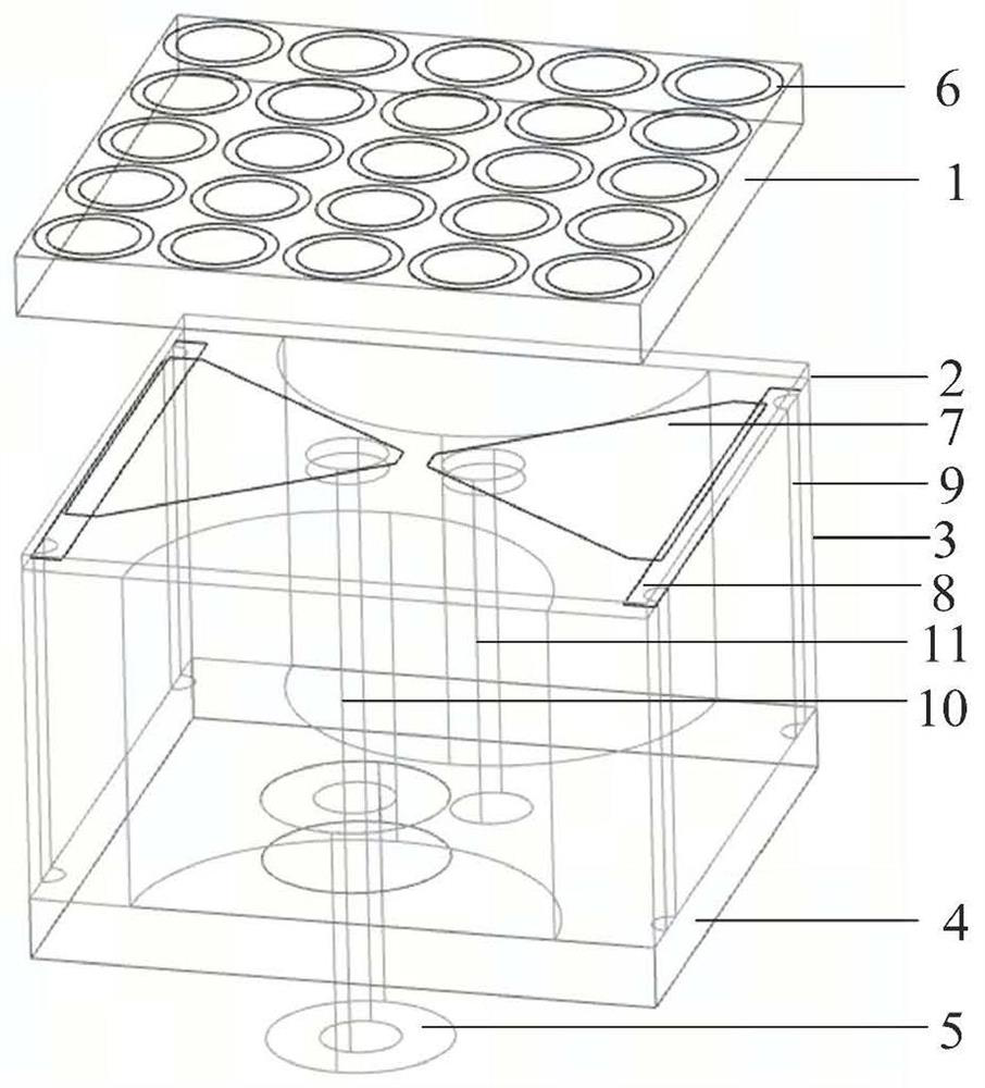
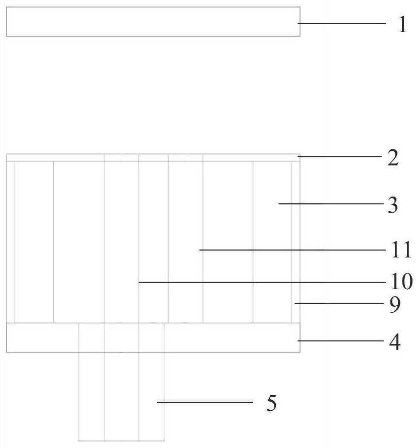
[0035] Such as figure 1 , figure 2 as shown, figure 1 is a structural stereoscopic view of the antenna unit, figure 2 is a structural sectional view of the antenna unit. The antenna unit includes an upper dielectric substrate 1 , a middle dielectric substrate 2 , a bottom dielectric substrate 3 , a metal ground 4 and a radio frequency connector 5 arranged from top to bottom.

[0036] The upper dielectric substrate 1 is arranged directly above the middle dielectric substrate 2, and a gap is provided between the upper dielectric substrate 1 and the middle dielectric substrate 2, and the upper dielectric substrate 1 and the middle dielectric substrate 2 The gaps in between can be filled with foam boards.

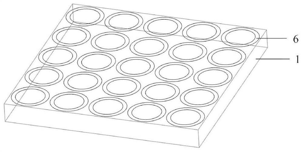
[0037] Such as image 3 as shown, image 3 It is a structural view of the upper dielectric substrate; the upper surface of the upper dielec...

Embodiment 2

[0050]Such as Figure 14 , Figure 15 As shown, the difference between the present embodiment and the first embodiment is that the shape of the decoupling metal strip 8 is circular, elliptical or other naturally conceivable shapes.

Embodiment 3

[0052] In this embodiment, an 8*8 array antenna composed of planar wide-bandwidth angular scanning phased array antenna elements is given to better illustrate the present invention.

[0053] Antenna front as Figure 16 As shown, the 8*8 array antenna has 8 units in the two dimensions of the arrangement, and the beam scanning at different angles can be realized by adjusting the arrangement of the array and the excitation of the ports. Using the antenna unit form of the present invention, any antenna array formed in any arrangement is an extension of this embodiment and falls within the protection scope of the present invention.


PUM


Abstract

The invention discloses a planar broadband wide-angle scanning phased-array antenna unit and a phased-array antenna. The planar broadband wide-angle scanning phased-array antenna unit comprises an upper dielectric substrate, a middle dielectric substrate, a bottom dielectric substrate, a metal ground and a radio frequency connector which are arranged from top to bottom, wherein periodically arranged matching rings are arranged on the upper surface of the upper dielectric substrate; a butterfly-shaped dipole is printed on the upper surface of the middle-layer dielectric substrate; a decoupling metal strip is arranged on the upper surface of the bottom dielectric substrate, decoupling metal through holes are formed in the two ends of the decoupling metal strip respectively, and the decoupling metal through holes penetrate through the bottom dielectric substrate to be connected with the metal ground and the decoupling metal strip. The radio frequency connector inner core passes through the metal ground, the bottom dielectric substrate and the middle dielectric substrate and is connected to the butterfly-shaped dipole. The short circuit metal through hole passes through the bottom dielectric substrate and the middle dielectric substrate and is connected to the butterfly-shaped dipole. The decoupling metal strips and the decoupling metal through holes are introduced, resonance points in an antenna band are eliminated, and the standing wave performance of the antenna during wide-angle scanning in the working bandwidth is improved.

Description

technical field [0001] The invention relates to the technical field of antennas, in particular to a planar wide bandwidth angular scanning phased array antenna unit and a phased array antenna. Background technique [0002] Phased array antennas are widely used in radar systems due to their outstanding performance and flexible working methods. With the in-depth application and development of technology, not only the requirements for its radiation characteristics such as broadband and wide-angle scanning have been greatly improved, but also for its application environment. In environments with severe vibrations such as wings and fuselages, it is still necessary to ensure the reliability and stability of the phased array antenna. As a result, planar phased array antennas laminated by multi-layer dielectric boards are gradually gaining favor, and the choice of dielectric board materials that are insensitive to temperature and high stability makes this type of unit form availabl...

Claims


Application Information

Patent Timeline
Patent Type & Authority Applications(China)
IPC IPC(8): H01Q1/36H01Q1/38H01Q1/48H01Q1/50
CPCH01Q1/36H01Q1/38H01Q1/48H01Q1/50
Inventor 王亚茹张小林王杰苗菁王一杰金谋平
Owner CHINA ELECTRONIC TECH GRP CORP NO 38 RES INST
Why Eureka
Try Eureka