Flat waveguide feed two-dimensional beam scanning antenna

A technology of waveguide feeding and beam scanning, which is applied in the directions of antenna arrays, antennas, and slot antennas that are powered independently, and can solve problems such as uneven microwave transmission, high antenna profile, and narrow operating bandwidth.

Active Publication Date: 2021-04-06
NAT UNIV OF DEFENSE TECH
View PDF3 Cites 2 Cited by
  • Summary
  • Abstract
  • Description
  • Claims
  • Application Information

AI Technical Summary

Problems solved by technology

[0004] The technical problem to be solved by the present invention is to provide a flat waveguide-fed two-dimensional beam scanning antenna, which overcomes the shortcomings of the existing helical array antennas, such as high p

Method used


Image

  • Flat waveguide feed two-dimensional beam scanning antenna
  • Flat waveguide feed two-dimensional beam scanning antenna
  • Flat waveguide feed two-dimensional beam scanning antenna

Examples


Embodiment Construction

[0056] The specific implementation manner of the present invention will be further described below in conjunction with the drawings and embodiments. The following examples are only used to illustrate the present invention, but not to limit the scope of the present invention.

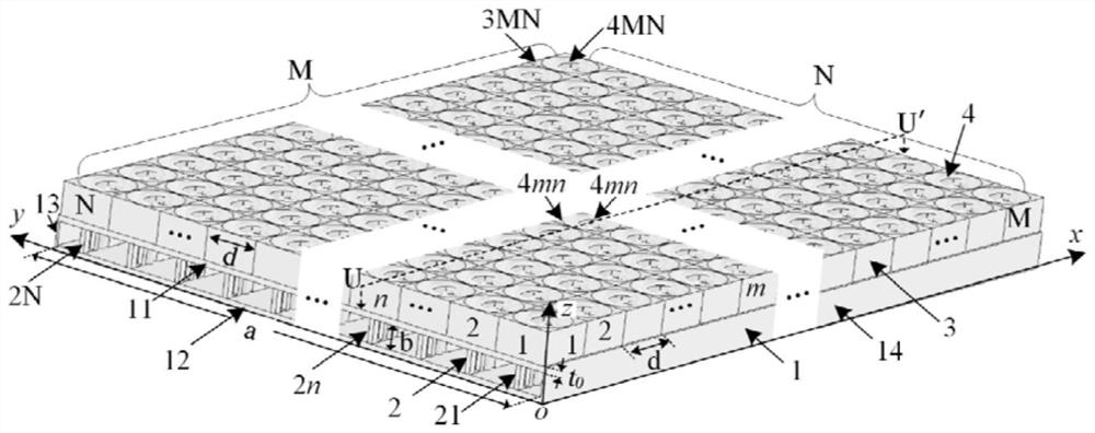
[0057] Such as figure 1 As shown, the present invention is an all-metal structure consisting of four parts. The first part is a flat waveguide 1, which is a special rectangular waveguide with extended wide sides; the second part is N baffles 2, and each baffle is a solid long rectangular plate The third part is M×N external cavities 3, each of which is cuboid in shape, and a circular channel with varying radius is drawn out in the center; the fourth part is M×N short helical antennas 4. Based on the Cartesian coordinate system, define the positive direction of the z-axis as up, the negative direction of the z-axis as down, the distance between up and down as height, the negative direction of the x-axis ...


PUM

PropertyMeasurementUnit
Wall thicknessaaaaaaaaaa
Widthaaaaaaaaaa

Abstract

The invention discloses a flat waveguide feed two-dimensional beam scanning antenna; the antenna is composed of a flat waveguide, N baffles, M*N outer cavities and M*N short spiral antennas; the baffle is a long rectangular plate; the outer cavity is a cuboid of which the center is provided with a radius-variable circular channel; the N baffles are inserted into the flat waveguide in the direction parallel to the x axis, so N+1 rectangular channels are formed in the flat waveguide, and the width of the N-1 rectangular channels in the middle is d; the M*N outer cavities are tightly arranged in a manner that square grids with the side length of d are parallel to the xoy plane, and the lower surfaces of the outer cavities are attached to the upper surface of the flat waveguide; and the M*N short helical antennas respectively pass through the M*N outer cavity circular channels and sequentially pass through the upper waveguide wall of the flat waveguide, the baffle plate and the lower waveguide wall of the flat waveguide. According to the method, defects of high profile, narrow working bandwidth, low power capacity and non-uniform microwave transmission of the existing spiral array antenna are overcome, the spiral antenna can be controlled to rotate in rows and columns, and two-dimensional scanning of wave beams is realized.

Description

technical field [0001] The invention relates to antennas in the technical field of high-power microwaves, in particular to a high-power microwave helical array antenna fed by a flat waveguide and capable of scanning two-dimensional beams. Background technique [0002] The high-power microwave antenna is an important tool to radiate the energy generated by the microwave source to space, and the performance of the antenna directly affects the application effect of the high-power microwave. In the context of the limited development of high-power microwave generation power, it is of great significance to study high-performance high-power microwave antennas. Due to the high power of high-power microwaves, it is difficult for a single antenna to meet the requirements of high gain and high power capacity at the same time, while array antennas can increase the antenna gain by increasing the number of sub-antennas, and can also distribute energy evenly to multiple sub-antennas to inc...

Claims


Application Information

Patent Timeline
IPC IPC(8): H01Q1/50H01Q13/10H01Q3/32H01Q1/52H01Q21/00H01Q21/06
CPCH01Q1/50H01Q13/10H01Q3/32H01Q1/52H01Q21/0006H01Q21/06
Inventor 袁成卫秦洪才张晓萍孙云飞张强许亮
Owner NAT UNIV OF DEFENSE TECH
Why Eureka
Try Eureka