Eureka AIR delivers breakthrough ideas for toughest innovation challenges, trusted by R&D personnel around the world.

Nanofluidic device

A nanofluidic control and flow channel technology, applied in the field of in-situ experimental instruments, can solve the problems of tedious manual operation, switching and inconvenience of operators, and achieve the effect of improving user experience, convenient use and high efficiency.

Pending Publication Date: 2021-04-09
XIAMEN CHIP NOVA TECH CO LTD
View PDF0 Cites 0 Cited by
  • Summary
  • Abstract
  • Description
  • Claims
  • Application Information

AI Technical Summary

Problems solved by technology

At present, the control of fluid flow, the switching of materials, and the reciprocating movement of fluid in the chip all require the operator to perform cumbersome manual operations and switching, which is very inconvenient

Method used


Image

  • Nanofluidic device
  • Nanofluidic device
  • Nanofluidic device

Examples


Embodiment 1

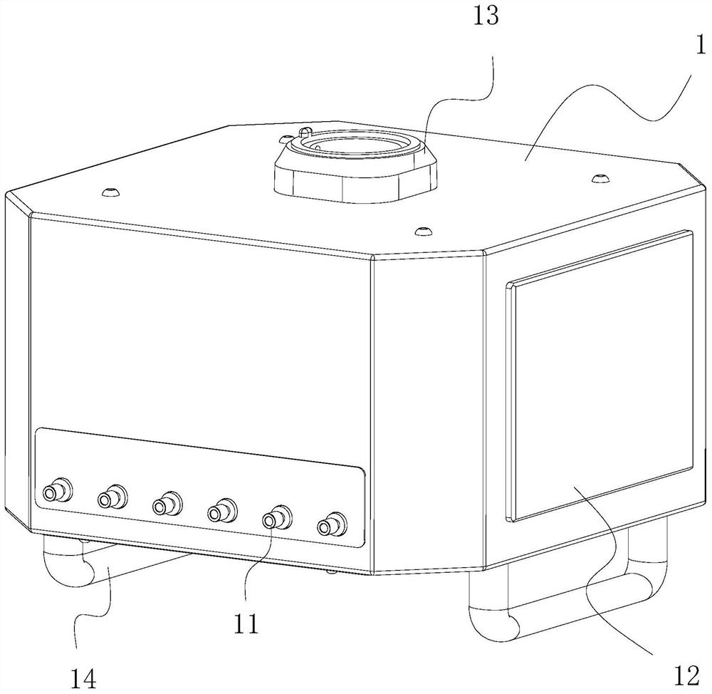
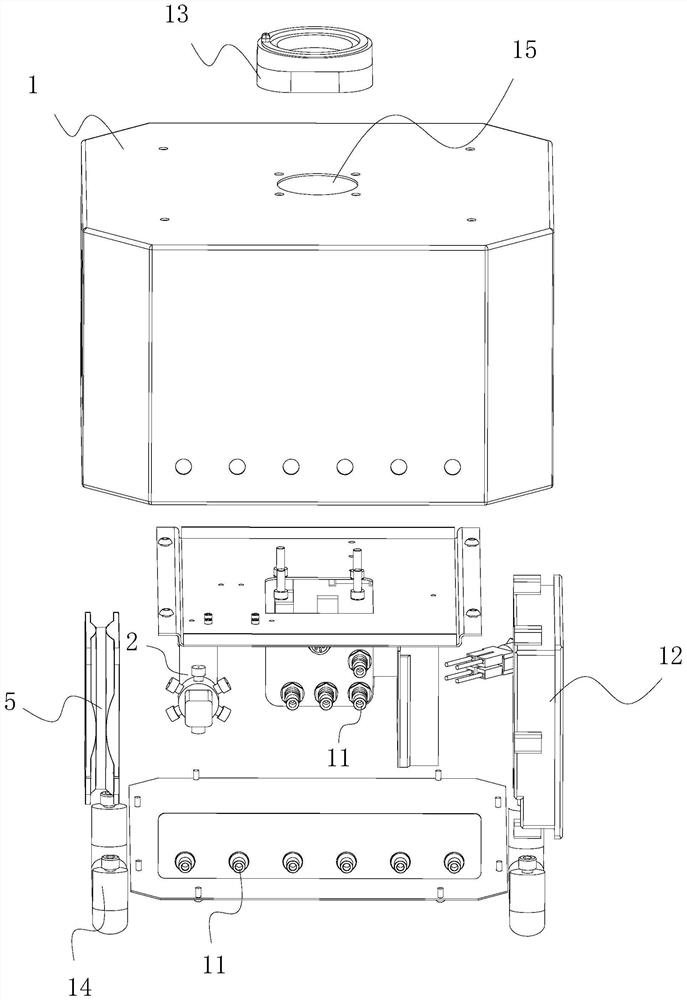
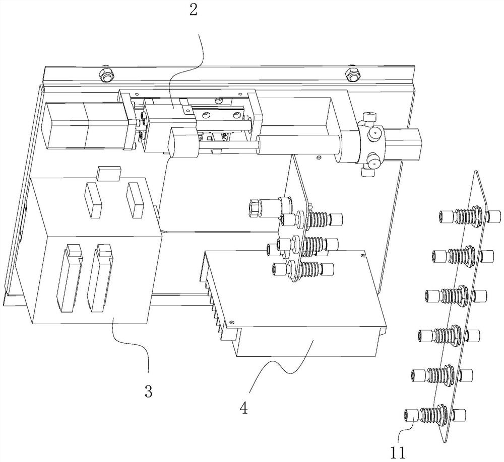
[0025] Such as Figures 1 to 5 As shown, a nanofluidic control device includes a casing 1 , a fluid control component 2 and a controller 3 are arranged inside the casing 1 , and the output terminal of the controller 3 is connected to the control input terminal of the fluid control component 2 . The controller 3 may be an existing PLC (Programmable Logic Controller, Programmable Logic Controller).

[0026] The fluid control assembly 2 has a flow channel switching valve 23 , a syringe 22 and a plurality of internal flow channel interfaces 21 . The channel switching valve 23 is used to switch the internal channel interface 21 communicating with the syringe 22: the internal rotation switching action of the channel switching valve 23 is controlled by the control signal provided by the controller 3, so that the fluid flows in from a specific internal channel interface 21 or flow out.

[0027] The casing 1 is provided with a plurality of external flow channel interfaces 11 , and di...


PUM


Abstract

The invention belongs to the technical field of in-situ experiment instruments, and particularly relates to a nanofluidic device which comprises a shell, a fluid control assembly and a controller are arranged in the shell, and the output end of the controller is connected with the control input end of the fluid control assembly; wherein the fluid control assembly is provided with a flow channel switching valve, an injector and a plurality of internal flow channel interfaces; the flow channel switching valve is used for switching the internal flow channel interfaces communicated with the injector; the shell is provided with a plurality of external flow channel connectors, and different internal flow channel connectors are connected with different external flow channel connectors respectively. Different external flow channel interfaces can be used for receiving different fluid materials, and switching of the different fluid materials is carried out through the fluid control assembly; the fluid control assembly can suck in and discharge fluid, so that the fluid moves back and forth in the chip. The fluid flow control, the material switching and the reciprocating motion of the fluid in the chip are all automatically completed by the fluid control assembly under the control of the controller without complex manual operations of a worker.

Description

technical field [0001] The invention belongs to the technical field of in-situ experimental equipment, and in particular relates to a nanofluid control device. Background technique [0002] When doing experiments on in-situ fluid chips, it is necessary to introduce fluid (gas or liquid) into the chip in real time in order to observe real-time physical or chemical changes. Since the space inside the fluidic chip needs to be very thin to form a very thin fluid layer, the electron transmission electron microscope can observe (too thick fluid layer will hinder the electron beam from penetrating), so the flow rate of the fluid needs to be very small (up to nanoliter level) ). [0003] Experimental procedures often require switching between multiple fluid materials. Depending on the chip usage, some experiments require the fluid to be able to move back and forth inside the chip. At present, the control of fluid flow, the switching of materials, and the reciprocating movement of...

Claims


Application Information

Patent Timeline
Patent Type & Authority Applications(China)
IPC IPC(8): B01L3/00
CPCB01L3/50273
Inventor 廖洪钢林国林
Owner XIAMEN CHIP NOVA TECH CO LTD
Why Eureka
Eureka Blog
Learn More