Water vapor treatment part, shower head and cleaning system
A technology for processing parts and water vapor, applied in the field of cleaning, can solve problems such as reducing air humidity, increasing the risk of other members of the family getting sick, and increasing the risk of illness for users
- Summary
- Abstract
- Description
- Claims
- Application Information
AI Technical Summary
Problems solved by technology
Method used
Image
Examples
Embodiment 1
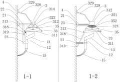
[0048] figure 1 middle, Picture 1-1 is an example diagram of the vapor treatment department / shower / washing system, Figure 1-2 It is another example diagram of the water vapor treatment unit / shower / cleaning system; the cleaning system includes: a shower; the shower includes: a hand shower 12, a mounting piece and a water vapor treatment unit 3, and the three are respectively adapted; the water source supply unit 3 It is connected with the hand shower 12 through the water supply pipe 15; the hand shower 12 has a water outlet 13 of any shape and / or any structure;
[0049] like Picture 1-1 As shown, the mounting piece is a combined mounting piece, including: a support piece 22, a fixing piece 21 and a mounting piece 23 with an adjustment function; Vertically connected vertical bars; the fixed member 21 is preferably an expansion bolt / expansion screw, which is adapted to the left end of the horizontal bar and fixed on the wall 4; the right end of the horizontal bar is fixed w...
Embodiment 2
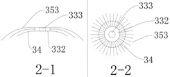
[0058] figure 2 middle, Figure 2-1 is the side view of the deflector, Figure 2-2 Yes Figure 2-1 The top view of the middle deflector; the deflector includes: an annular turntable 332, a filamentary flow guide 353; the center of the annular turntable 332 has a through hole 333 adapted to the rotation shaft / rotation shaft; the outer periphery of the turntable 332, etc. There are filamentary flow guides 353 with a layer number greater than or equal to one radially distributed; one end of the filamentary flow guides 353 is fixedly connected to the turntable 332, and the lower surface has a raised annular flow guide with a number greater than or equal to one Part 34; located on the periphery of the rotating disk 332 and the center points of the two are on the same straight line; the guide part 34 has the function of shaping and / or draining and / or making the filamentary guide device 353 partially bend downward; or the outer periphery of the circular rotating disk 332 The fili...
Embodiment 3
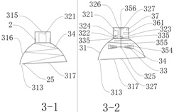
[0061] image 3 middle, Figure 3-1 , Figure 3-2 They are respectively an example diagram of the interior of the housing described in the present invention;
[0062] like Figure 3-1As shown, the assembled shell / combined shell includes: the upper shell 315 and the lower shell 316 are two hollow shells with cavities, and the two shells are respectively fitted and connected through the mounting part 2; The cross-section is H-shaped, the two ends of the bottom are splayed, and the outer circumference has external threads. The inner walls of the upper shell 315 and the lower shell 316 have internal threads that are compatible with the mounting part 2, and the three are detachable connections. There is a detachable mask 317 at the bottom of the lower housing 316, and one side of the mask 317 has a liquid outlet 313, which communicates with the inside of the housing; the mask 317 also has an air inlet connected to the inside of the housing, preferably with some cross-sections of...
PUM
 Abstract
Description
Claims
Application Information
 - R&D
- Intellectual Property
- Life Sciences
- Materials
- Tech Scout
- Unparalleled Data Quality
- Higher Quality Content
- 60% Fewer Hallucinations
Browse by: Latest US Patents, China's latest patents, Technical Efficacy Thesaurus, Application Domain, Technology Topic, Popular Technical Reports.
© 2025 PatSnap. All rights reserved.Legal|Privacy policy|Modern Slavery Act Transparency Statement|Sitemap|About US| Contact US: help@patsnap.com


