Ultrasonic cleaning device with pre-cleaning function

A cleaning device, ultrasonic technology, applied in the field of ultrasonic cleaning, can solve the problems of reducing the number of times of use, increasing the time of cleaning, increasing the cost of cleaning, etc., to achieve the effect of reducing cleaning costs, increasing the number of times of use, and reducing dirt

Active Publication Date: 2021-04-09
SHENZHEN RUIDEFENG TECH
View PDF10 Cites 11 Cited by
  • Summary
  • Abstract
  • Description
  • Claims
  • Application Information

AI Technical Summary

Problems solved by technology

[0003] At present, when the existing ultrasonic cleaning device with pre-cleaning function cleans the mechanical parts, it usually puts the mechanical parts to be cleaned directly into the ultrasonic cleaning tank. However, there will be a lot of dirt on the surface of the mechanical parts. The cleaning time is increased, and the number of times of using the special cleaning agent in the ultrasonic cleaning tank is reduced, which greatly increases the cleaning cost

Method used


Image

  • Ultrasonic cleaning device with pre-cleaning function
  • Ultrasonic cleaning device with pre-cleaning function
  • Ultrasonic cleaning device with pre-cleaning function

Examples


Embodiment 1

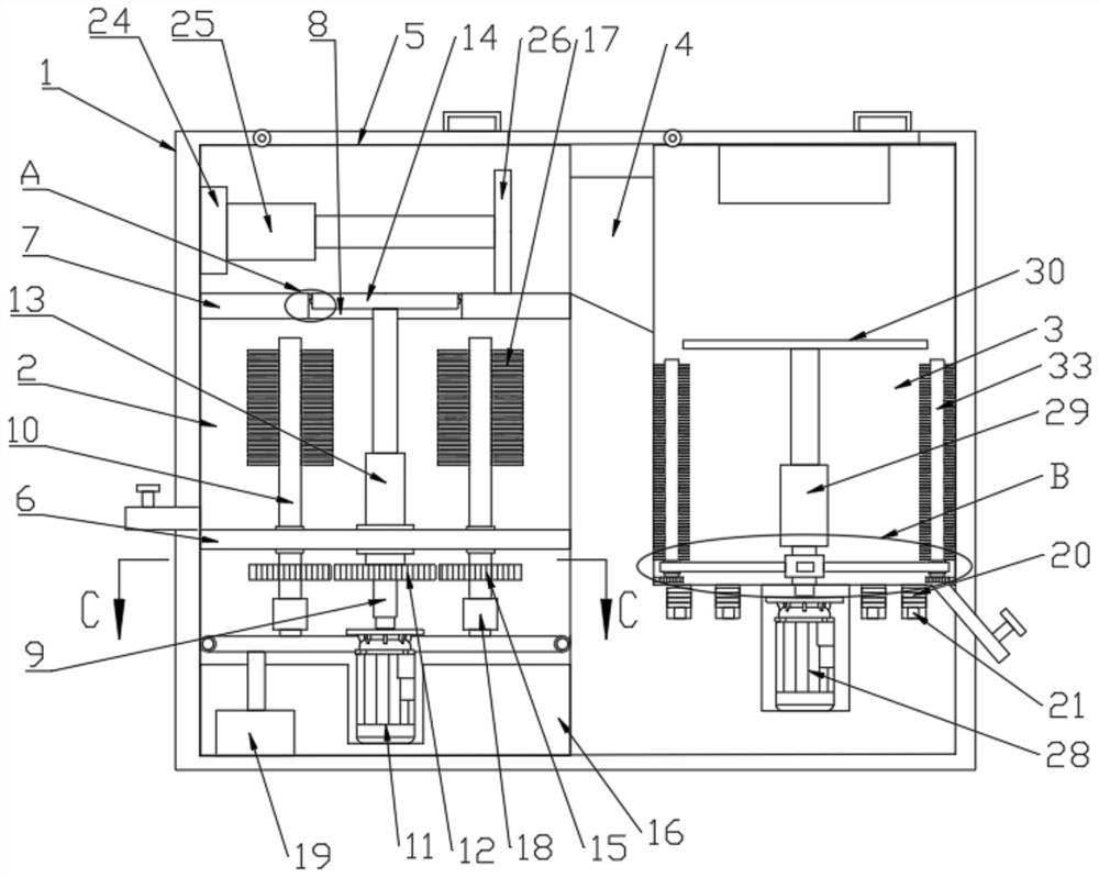
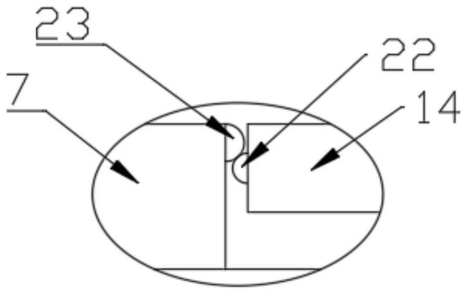
[0026] see Figure 1-7 , an ultrasonic cleaning device with a pre-cleaning function, including a cleaning box 1, a first cleaning cabin 2 and a second cleaning cabin 3 are arranged in the cleaning box 1, and the first cleaning cabin 2 and the second cleaning cabin 3 are provided with water outlets at the bottom of the side, and the top of the side of the first cleaning chamber 2 close to the second cleaning chamber 3 is provided with a through hole 4, and the top surface of the cleaning box 1 is located between the first cleaning chamber 2 and the second cleaning chamber. 3 positions are hingedly provided with a box cover 5, the first cleaning compartment 2 is provided with a first partition 6, and the first cleaning compartment 2 is fixedly provided with a second partition 7 above the first partition 6, The second dividing plate 7 is provided with a placement hole 8, and the top surface of the second dividing plate 7 is at the same horizontal position as the bottom of the thr...

Embodiment 2

[0032] This embodiment has been improved on the basis of Embodiment 1, specifically:

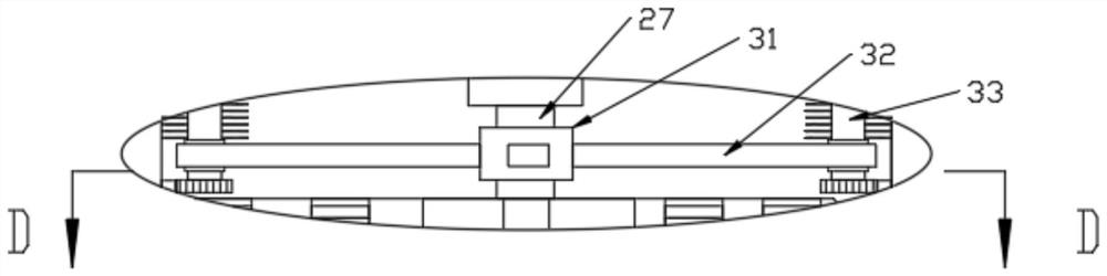
[0033] A cleaning mechanism is also provided in the second cleaning chamber 3, and the cleaning mechanism includes a third rotating shaft 27. The third rotating shaft 27 is sealed and rotationally connected with the bottom surface of the second cleaning chamber 3, and the third rotating shaft 27 is arranged in the box. Driven by the second motor 28, the top of the third rotating shaft 27 is connected with the loading plate 30 through the third telescopic rod 29, and the outer wall of the third rotating shaft 27 is fixedly provided with a rotating block 31, and the outer wall of the rotating block 31 is fixed A connecting plate 32 is provided, the end of the connecting plate 32 is rotatably connected with a cleaning rod 33, the cleaning rod 33 is uniformly provided with cleaning brushes 17, and the cleaning rod 33 is fixedly sleeved with a third gear 34, the The inner wall of the second clean...


PUM


Abstract

The invention discloses an ultrasonic cleaning device with a pre-cleaning function. The ultrasonic cleaning device with the pre-cleaning function comprises a cleaning box, a first cleaning bin and a second cleaning bin are arranged in the cleaning box, a pre-cleaning mechanism is arranged in the first cleaning bin, an ultrasonic generator and an ultrasonic transducer are arranged at the bottom of the second cleaning bin, a drying mechanism is arranged at the top of the second cleaning bin, a cleaning mechanism is further arranged in the second cleaning bin, dirt on the surfaces of mechanical parts can be cleaned by arranging the pre-cleaning mechanism, some hidden positions, difficult to clean, of the mechanical parts can be cleaned in cooperation with ultrasonic waves emitted by an ultrasonic generator and an ultrasonic transducer in the second cleaning bin, the phenomenon that an existing ultrasonic cleaning device directly cleans mechanical parts, and consequently the cleaning efficiency is low is avoided, dirt on the mechanical parts is reduced after the mechanical parts are pre-cleaned, the use frequency of a special cleaning agent is indirectly increased, and therefore the cleaning cost is reduced.

Description

technical field [0001] The invention relates to the technical field of ultrasonic cleaning, in particular to an ultrasonic cleaning device with a pre-cleaning function. Background technique [0002] During the processing and production of mechanical parts, they often need to go through many processes. There will be oil, debris and other impurities on the surface and in the holes, so they need to be cleaned or cleaned. Ultrasonic cleaner is an instrument used to remove pollutants. It converts the sound energy of the power ultrasonic frequency source into mechanical vibration through the transducer to clean items, and is widely used in various fields. [0003] At present, when the existing ultrasonic cleaning device with pre-cleaning function cleans the mechanical parts, it usually puts the mechanical parts to be cleaned directly into the ultrasonic cleaning tank. However, there will be a lot of dirt on the surface of the mechanical parts. The cleaning time is increased, and ...

Claims


Application Information

Patent Timeline
Patent Type & Authority Applications(China)
IPC IPC(8): B08B1/02B08B3/08B08B3/12B08B9/087B08B13/00F26B21/00
CPCB08B1/002B08B1/02B08B3/08B08B3/12B08B9/087B08B13/00F26B21/001F26B21/004
Inventor 丁晓波
Owner SHENZHEN RUIDEFENG TECH
Why Eureka
Try Eureka