Machining pipe winding device
A mechanical processing and pipe winding technology, which is applied in the direction of mechanical equipment, metal processing, metal processing equipment, etc., can solve the problems of low efficiency, high price, and poor versatility of manual tooling winding, and achieve improved service life, high versatility, The effect of reducing drag
- Summary
- Abstract
- Description
- Claims
- Application Information
AI Technical Summary
Problems solved by technology
Method used
Image
Examples
Embodiment 1
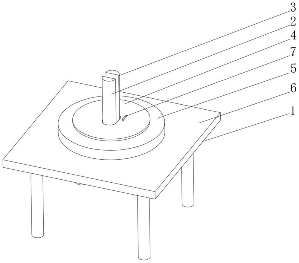
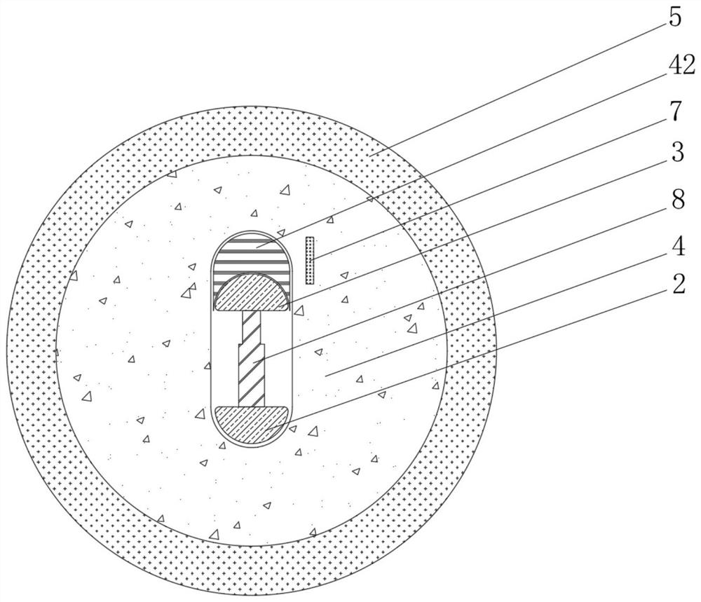
[0041]SeeFigure 1-2 The present invention provides a technical solution: a mechanical processing winding device including a base fixing wheel 2, a moving wheel 3, a protective disk 4, a rotary disk 5, and a base 6, a machining windout device body 1, a protective disk 4 includes a carrier disk 41, inner slide of the carrier disk 41, the upper fixation of the upper fixation of the upper fixation of the carrier disk 41, the inner side of the fixing wheel 2 is fixedly connected to the hydraulic rod 8, and the hydraulic rod is away One end of the fixing wheel 2 extends the inside of the moving wheel 3 and is fixed to the movable wheel 3, and the bottom portion of the rotary disc 5 is fixed to the top of the guard disk 4, and the bottom portion of the fixing wheel 2 is fixed to the internal fixed connection, The bottom of the active wheel 3 extends to the inside of the turret 5 and slides to the wheel disk 5.
[0042]When used, the user is debugged according to the inversion diameter of the ...
Embodiment 2
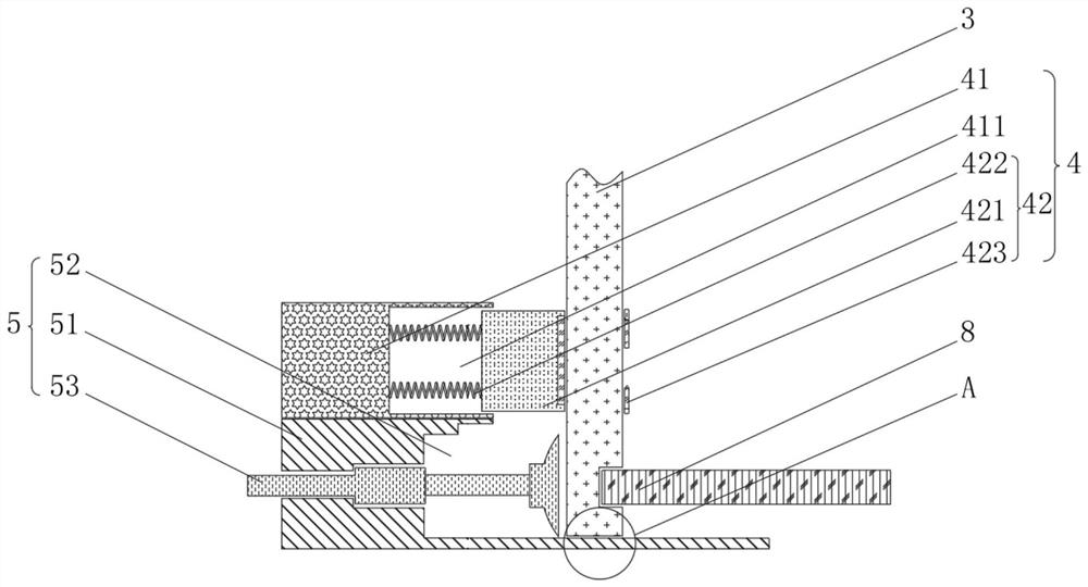
[0044]SeeFigure 1-5 Based on the first example, the present invention provides a technical solution: the anti-clamping mechanism 42 includes a bonding plate 421, and the inner portion of the carrier disc 41 is opened, and the outer side of the bonding plate 421 and the bonding groove 411. The internal sliding connection, the left side of the bonding plate 421 is fixedly connected to the cartridge spring 422, the left end of the cartridge spring 422 is fixed to the inside of the bonding groove 411, and the inner side of the bonding plate 421 is fixedly connected to the collision block 423.
[0045]The rotary disc 5 includes a stress disk 51, and the inside of the force disk 51 is provided with a force groove 52, and the inside of the force groove 52 is provided with a debug mechanism 53, and the debug mechanism 53 is located on the left side of the active wheel 3, the force disk 51. The bottom of the slider 511 is provided, and the middle portion of the sliding groove 511 is provided wi...
Embodiment 3
[0050]SeeFigure 1-7Based on the first and embodiment 2, the present invention provides a technical solution: the debug mechanism 53 includes a mash block 531, the outer side of the inlay block 531 and the inner wall of the force groove 52, an internal thread of the inlaid block 531. The inside of the detection rod 532 is connected, the inside of the detection lever 532 is fixedly connected to the rotary device 533, and the right end of the detection lever 532 is fixedly connected to the support block 534, and the right side of the support block 534 is provided with a buffer mechanism A.
PUM
 Abstract
Description
Claims
Application Information
 - R&D
- Intellectual Property
- Life Sciences
- Materials
- Tech Scout
- Unparalleled Data Quality
- Higher Quality Content
- 60% Fewer Hallucinations
Browse by: Latest US Patents, China's latest patents, Technical Efficacy Thesaurus, Application Domain, Technology Topic, Popular Technical Reports.
© 2025 PatSnap. All rights reserved.Legal|Privacy policy|Modern Slavery Act Transparency Statement|Sitemap|About US| Contact US: help@patsnap.com


