Circuit board welding device

A technology for welding devices and circuit boards, which is applied in the direction of electric heating devices, auxiliary devices, welding equipment, etc., can solve the problems of uncoiled cables, etc., and achieve the effects of easy lifting, reduced damage, and improved practicability

Inactive Publication Date: 2021-04-09
永康市质量技术监测研究院
View PDF11 Cites 3 Cited by
  • Summary
  • Abstract
  • Description
  • Claims
  • Application Information

AI Technical Summary

Problems solved by technology

[0009] The purpose of the present invention is to provide a circuit board welding device to

Method used


Image

  • Circuit board welding device
  • Circuit board welding device
  • Circuit board welding device

Examples


Embodiment 1

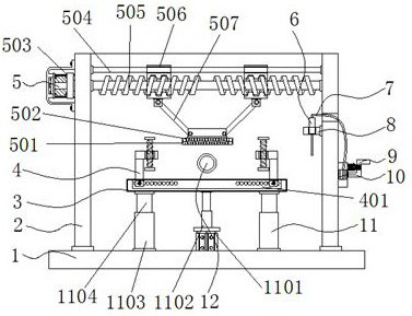
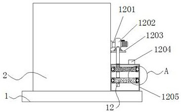
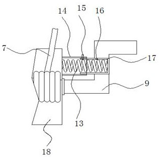
[0035] Example 1: See Figure 1-6 , a circuit board welding device, comprising a base plate 1 and a support frame 2, the two sides and one end of the top of the base plate 1 are respectively fixedly connected with the support frame 2, the top of one side of the support frame 2 is provided with a preheating mechanism 5, the top of the base plate 1 A workbench 3 is provided, a limit structure 4 is provided on both sides of the top of the workbench 3, a lifting mechanism 11 is provided between the bottom plate 1 and the support frame 2, and a support block 8 is fixedly connected to one side of the support frame 2, and the support block 8 The interior of the welding head 6 is provided with a cable 7 fixedly connected to the top of the welding head 6, one end of the support frame 2 is provided with a purification mechanism 12, and one side of the support frame 2 is provided with a winding structure;

[0036] see Figure 1-6 , a circuit board welding device also includes a winding ...

Embodiment 2

[0039] Embodiment 2: The limit structure 4 is composed of a chute 401, a limit hole 402, a limit plate 403, a spiral groove 404, a screw rod 405, a support rod 406, a limit bolt 407 and a slider 408, and the chute 401 is fixedly connected Inside the workbench 3, the support rod 406 is arranged on both sides of the top of the workbench 3, and the inside of one side of the support rod 406 is fixedly connected with a spiral groove 404, and the inside of the spiral groove 404 is provided with a screw rod 405, and the bottom of the screw rod 405 The end is fixedly connected with the limit plate 403, the bottom end of the support rod 406 is fixedly connected with a slider 408, the inside of the slider 408 is fixedly connected with the limit hole 402, and the inside of the limit hole 402 is provided with a limit bolt 407;

[0040] The limiting holes 402 are respectively fixedly connected to the inside of the chute 401 and the slide block 408, the slide block 408 is arranged inside the...

Embodiment 3

[0042] Embodiment 3: The preheating mechanism 5 is composed of a preheating plate 501, a heating wire 502, a servo motor 503, a slide rod 504, a screw shaft 505, a screw sleeve 506, a limit rod 507, an installation block 508 and a connecting block 509. The servo motor 503 is arranged on the top of the other side of the support frame 2, the model of the servo motor 503 is SMG80-M02430, the output end of the servo motor 503 is provided with a screw shaft 505, and the top of the screw shaft 505 is provided with a slide bar 504, the slide bar 504 and The screw shaft 505 is sleeved with a screw sleeve 506, the bottom end of the screw sleeve 506 is fixedly connected with a mounting block 508, the bottom end of the mounting block 508 is provided with a connecting block 509, and the bottom end of the connecting block 509 is fixedly connected with a preheating plate 501 , the inside of the preheating plate 501 is provided with a heating wire 502, the model of the heating wire 502 is OCR...


PUM


Abstract

The invention discloses a circuit board welding device, and particularly relates to the technical field of welding equipment. The circuit board welding device comprises a bottom plate and supporting frames, wherein the two sides and one end of the top end of the bottom plate are fixedly connected with the supporting frames correspondingly, a preheating mechanism is arranged at the top end of one side of each supporting frame, and a workbench is arranged at the top end of the bottom plate. According to the circuit board welding device, by arranging an exhaust pipe, an exhaust fan, a supporting plate, a gas outlet, a purifying box, an activated carbon particle plate, a photocatalyst plate, a cross-shaped clamping block and a cross-shaped clamping groove, harmful gas can be generated when a welding head is used for welding a circuit board, the exhaust fan is started, and the exhaust fan sucks the gas into the inner bottom end of the purifying box through the exhaust pipe; and because the activated carbon particle plate and the photocatalyst plate are arranged in the purifiying box, when gas gets away from the purifiying box through the gas outlet, the activated carbon particle plate and the photocatalyst plate can purify the gas purified to prevent the gas from pulluting the environment and further prevent the gas from causing harm to the bodies of workers.

Description

technical field [0001] The invention relates to the technical field of welding equipment, in particular to a circuit board welding device. Background technique [0002] With the rapid development of the electronics industry in recent years, circuit board welding technology has also developed rapidly. Since more and more electronic products use circuit boards, users have higher and higher requirements for circuit board welding. The circuit board welding device does not effectively limit the circuit board and does not rewind the cable. [0003] In the process of realizing the present invention, the inventors have found that at least the following problems in the prior art have not been resolved: [0004] (1) The traditional circuit board welding device does not rewind the cables connected to the welding head, which may easily cause the cables to be entangled; [0005] (2) The traditional circuit board welding device does not effectively limit the circuit board to be welded, ...

Claims


Application Information

Patent Timeline
IPC IPC(8): B23K3/047B23K3/08B65H75/38B65H75/44
CPCB23K3/047B23K3/08B23K3/087B65H75/38B65H75/44B65H75/4492B65H2701/34
Inventor 胡帅徐健康耿童昱朱正兵李垚磊周梦幽杨仲辉
Owner 永康市质量技术监测研究院
Why Eureka
Try Eureka