A kind of ti alloy pipe fitting welding method and welding device

A pipe fitting welding and alloying technology, which is applied in the direction of welding equipment, welding equipment, auxiliary equipment, etc., can solve the problems of cracks in the heat-affected zone, poor weldability of titanium alloys, unfavorable continuous welding, etc., and achieve the effect of fast cutting and guaranteed welding effect

Active Publication Date: 2021-06-15
江苏赛福隆智能装备有限公司
View PDF0 Cites 0 Cited by
  • Summary
  • Abstract
  • Description
  • Claims
  • Application Information

AI Technical Summary

Problems solved by technology

[0003] However, titanium alloys have poor weldability and serious welding defects, which bring great difficulties to the application of titanium alloys. This is mainly reflected in the fact that with the increase of welding temperature, the ability of titanium alloys to absorb hydrogen, oxygen, and nitrogen gradually increases, resulting in embrittlement of welded joints. The impact toughness and plasticity of its structure are reduced, and cracks are generated in the heat-affected zone
[0004] At present, the welding of titanium alloy pipe fittings is mainly done by welding torch and dragging cover, and only the ventilation protection is carried out around the welding torch. Welding requires other rotating pipe fittings to be welded, which is not conducive to continuous welding and increases the difficulty of welding

Method used


Image

  • A kind of ti alloy pipe fitting welding method and welding device
  • A kind of ti alloy pipe fitting welding method and welding device
  • A kind of ti alloy pipe fitting welding method and welding device

Examples


Embodiment 1

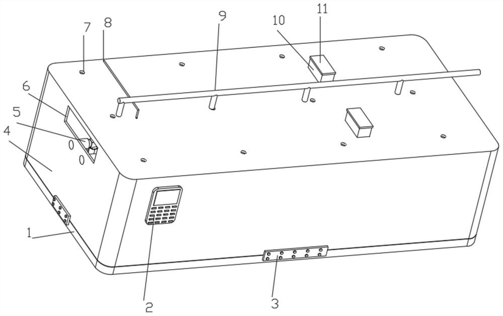
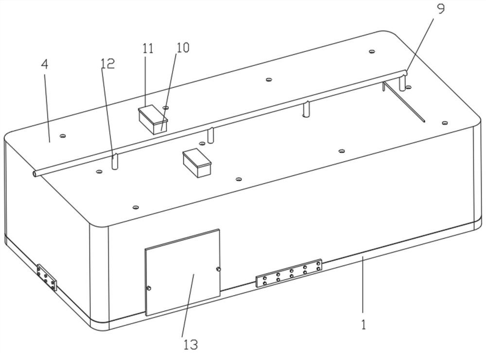
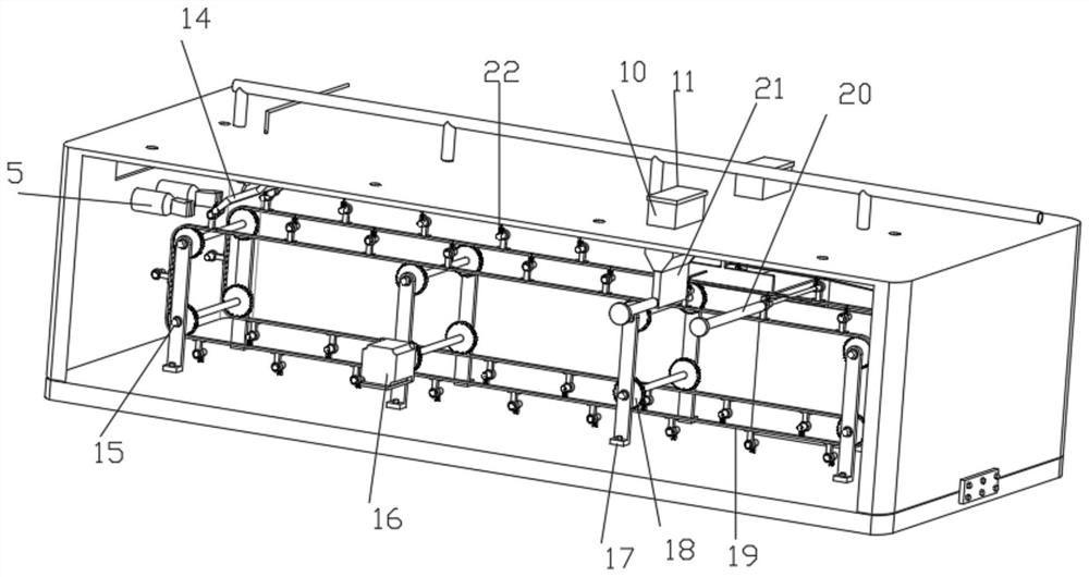
[0050] Such as figure 1 , 2 , 3, 4, 5, 6, 7, 9, and 10 show a Ti alloy pipe welding device, including a base 1, a controller 2, a welding torch connection cable 8, a horizontal pipe 9, a gas injection pipe 12 and a welding torch 24, the base The top of 1 is connected with an intermittent moving structure for the intermittent movement of Ti alloy pipe fittings. The intermittent moving structure includes a rotating shaft 15, a stepping motor 16, a support plate 17, a ring gear 18, a chain 19, a fixed sleeve 22, a support block 36 and The one-way bearing 37, the support plate 17 is symmetrically and evenly fixed on the top of the base 1 by bolts, the upright position of the support plate 17 is connected with two groups of identical rotating shafts 15 through the connected bearings to rotate up and down, and the outer parts of one group of rotating shafts 15 end is fixedly connected with the output end of the stepper motor 16, and the stepper motor 16 is fixedly installed on the ...

Embodiment 2

[0058] Embodiment 2 is a further improvement to Embodiment 1.

[0059] Such as Figure 8 The shown fixing structure comprises an n-shaped plate 38, a straight plate 39, a round bar 40, a spring 41, an arc-shaped pressing plate 42 and a straight groove 43. The top of the n-shaped plate 38 is fixedly connected with an n-shaped plate 38, the straight hole of the n-shaped plate 38 is fitted and slidably connected with a straight plate 39, the inner wall of the straight plate 39 is fixedly connected with a round rod 40 for driving the straight plate 39 to move, and the bottom of the straight plate 39 is fixedly connected with a Arc-shaped pressing plate 42, the diameter of the bottom of the arc-shaped pressing plate 42 is the same as the diameter of the inner ring of the fixed sleeve 22, the top of the arc-shaped pressing plate 42 and the inner top of the n-shaped plate 38 are fixedly connected with a spring 41, and the spring 41 is sleeved on the straight plate On the outside of ...

Embodiment 3

[0061] Embodiment 3 is a further improvement to Embodiment 1.

[0062] Such as Figure 4 , 10As shown, the outer wall of the welding gap correction plate 26 is connected with a push structure for pushing the round rod 40 to move, the push structure includes an L-shaped support rod 27 and an oblique guide rod 28, and the right end of the L-shaped support rod 27 is fixedly connected with an oblique guide When the right end of the rod 28 and the oblique guide rod 28 contact the round rod 40, the oblique guide rod 28 pushes the round rod 40 to move upwards and move the Ti alloy pipe to the L-shaped support rod 27, and the right end of the L-shaped support rod 27 is arranged on the first electric motor. The right end of the push rod 20, the left end of the L-shaped support rod 27 is located at the left end of the third electric push rod 31, when the round rod 40 contacts the L-shaped support rod 27, the arc-shaped pressing plate 42 is separated from the Ti alloy pipe fitting, and ...


PUM


Abstract

The invention discloses a Ti alloy pipe fitting welding method and a welding device, which relate to the field of welding equipment and include a base. The top of the base is connected with an intermittent moving structure for intermittent movement of Ti alloy pipe fittings; the top of the base is connected with a full The welding chamber surrounded by argon gas is welded, and rubber gloves for hand protection are fixedly connected in the straight holes opened symmetrically on the left side wall of the welding chamber, and the welding chamber is fixedly connected with an observation window for observation above the rubber gloves , the top of the welding chamber is sequentially connected with a welding mechanism, a rotating structure, a feeding structure and a feeding structure from left to right. The Ti alloy pipe fittings of the present invention can be rotated and continuously welded rapidly without the assistance of other staff, which is conducive to continuous welding , to reduce the difficulty of welding.

Description

technical field [0001] The invention relates to the field of welding equipment, in particular to a welding method and a welding device for Ti alloy pipe fittings. Background technique [0002] Titanium alloy has the advantages of low density, high tensile strength, and good corrosion resistance, but its chemical properties are extremely active at high temperatures. Above 200 ° C, titanium has a strong absorption effect on hydrogen, oxygen, and nitrogen in the air, so When welding titanium alloys, the welding high-temperature area needs to be protected by inert gas, and the weld pool, heat-affected zone, and base metal high-temperature area should be protected to prevent hydrogen, oxygen, nitrogen and other gases in the air from entering the weld. cause deterioration of weld performance. [0003] However, titanium alloys have poor weldability and serious welding defects, which bring great difficulties to the application of titanium alloys. This is mainly reflected in the fac...

Claims


Application Information

Patent Timeline
Patent Type & Authority Patents(China)
IPC IPC(8): B23K37/053B23K37/047B23K37/00B23K31/02
CPCB23K31/02B23K37/00B23K37/047B23K37/053
Inventor 谢杰王凡斌谢兴建王晶晶
Owner 江苏赛福隆智能装备有限公司
Why Eureka
Try Eureka