
Garbage can and cleaning and drying method thereof

A technology for trash cans and barrels, applied in the field of trash cans, can solve the problems of inconvenient removal of garbage, impact on garbage disposal, and high labor costs, so as to improve the efficiency and effect of cleaning, ensure the effect and area of ​​wetting, and improve the moistening effect. The effect of wet efficiency

Active Publication Date: 2021-04-09
章鸿扬
View PDF15 Cites 3 Cited by
  • Summary
  • Abstract
  • Description
  • Claims
  • Application Information

AI Technical Summary

Problems solved by technology

[0002] Trash can is a container for storing garbage or waste, which is widely used in public places such as residential areas, parks, etc., and is an indispensable appliance in people's lives. However, half of the existing trash cans All are only the upper opening (for putting in garbage), but this method will have certain inconvenience when taking out the garbage from the garbage can. At the same time, the existing garbage cans are generally located outdoors, so they are very easy to damage , resulting in the leakage of the garbage inside, which will pollute the environment;
[0003] Not only that, when the existing trash cans are in use, they need to be cleaned to ensure the cleanliness of the trash cans. However, the existing cleaning methods mainly use manual processing, which has low efficiency, poor effect and The defect of high labor cost;
[0004] In addition, in hot weather, the garbage in the garbage can is easily rotted and degraded, which will cause the temperature in the garbage can to rise and generate a lot of peculiar smell, which will not only affect the surrounding environment, but also easily cause the garbage to spontaneously ignite. a certain risk;
[0005] When it is cold, it is very easy to freeze in the garbage can, therefore, it will cause the garbage to solidify in the garbage can, thus affecting the treatment of garbage

Method used


Image

  • Garbage can and cleaning and drying method thereof
  • Garbage can and cleaning and drying method thereof
  • Garbage can and cleaning and drying method thereof

Examples


Embodiment 1

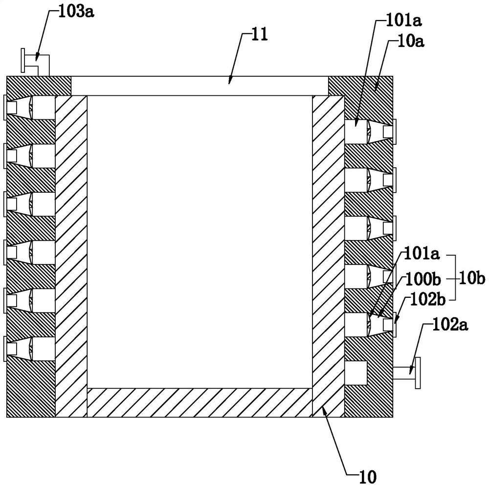
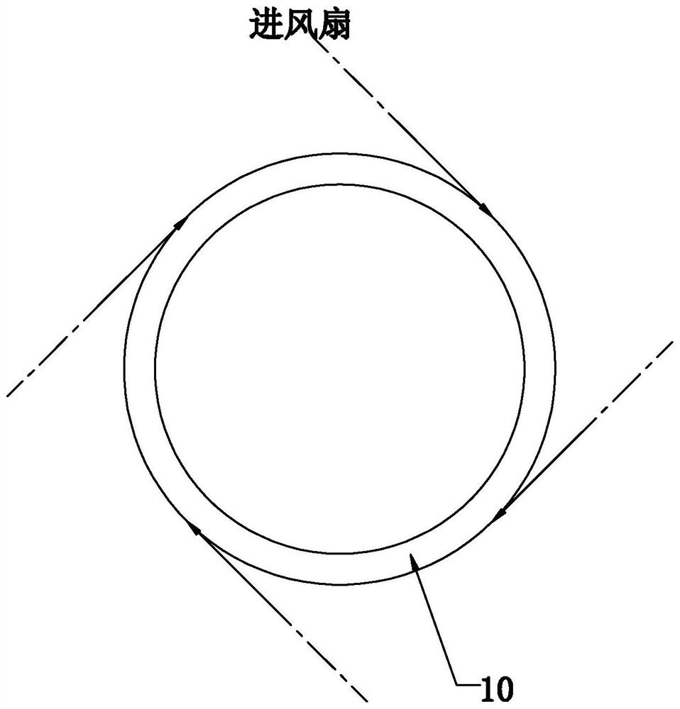
[0047] Such as Figure 1-Figure 2 As shown, the present invention provides a trash can, including a barrel body 10 and a barrel cover 11 installed on the top of the barrel body 10, and in a specific embodiment of the present invention, includes an outer barrel containing the barrel body 10; wherein, the The outer barrel includes an outer barrel body 10a with a cavity compatible with the barrel body 10, a heat exchange tank 101a that is recessed on the inner wall of the cavity of the outer barrel body 10a and extends spirally, and is provided on the outer barrel body 10a. The air inlet 102a and the air outlet 103a on the barrel body 10a and communicated with the heat exchange tank 101a and several intervals are installed in the heat exchange tank 101a and direct the air in the heat exchange tank 101a to the outer wall of the barrel body 10 A flow guide module 10b guided in a tangential direction; wherein, the flow guide module 10b includes an opening 100b provided on the outer ...

Embodiment 2

[0050] The difference between embodiment 2 and embodiment 1 is that

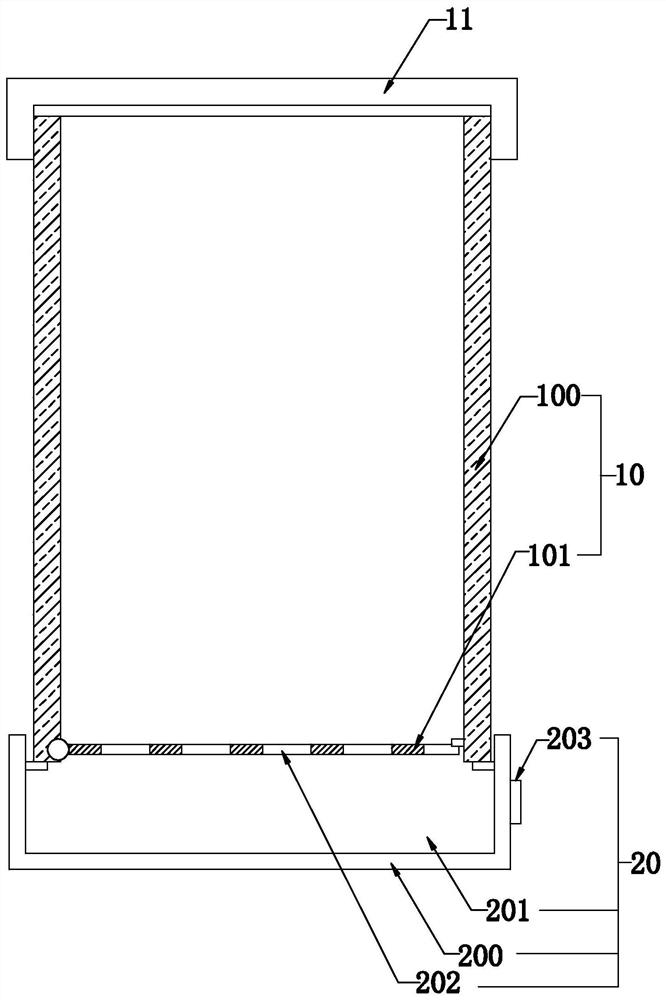
[0051] Such as image 3 As shown, in a specific embodiment of the present invention, the barrel body 10 includes a body 100 with an opening at the upper end and a lower end, and a body 100 that is provided at the opening at the lower end of the body 100 and is hinged to the body 100 on any side and at least one side is The support plate 101 detachably connected with the body 100; when the support plate 101 is turned over based on the hinge joint with the body 100 and the opening at the lower end of the body 100 is opened, the garbage in the body 100 can pass through the lower end of the body 100 Opening to discharge.

[0052] In a specific embodiment of the present invention, it also includes a drainage structure 20 arranged at the bottom of the body 100 and used to support the body 100; wherein, the drainage structure 20 includes a base 201 having a cavity 200 and used to support the body 100, The drainag...

Embodiment 3

[0057] Embodiment 3, the difference with embodiment 2 is:

[0058] Such as Figure 4-Figure 10 As shown, in the specific embodiment of the present invention, it also includes a water storage body 30 installed on the body 100 and a cleaning device installed on the bucket cover 11 and supplied with water through the water storage body 30; wherein, the cleaning device includes At least three transmission wheels 310 that are rotatably connected to the bucket cover 11 and distributed at equidistant intervals from the axis of the body 100 and driven by a motor 311, a synchronous transmission belt 312 that is transmission connected to each transmission wheel 310, and several transmission wheels installed on the The water spray device 313 on the synchronous transmission belt 312 and between the adjacent transmission wheels 310 and the water supply part 314 installed on the bucket cover 11 and used to supply water to each water spray device 313 at the same time; wherein, the water supp...


PUM


Abstract

The invention relates to a garbage can and a cleaning and drying method thereof. The garbage can comprises a can body and a can cover mounted at the top end of the can body, and the garbage can is characterized by comprising an outer can for accommodating the can body; and the outer can comprises an outer can body provided with a cavity matched with the can body, a heat exchange groove which is formed in the inner wall of the cavity of the outer can body in a sunken manner and extends spirally, an air inlet and an air outlet which are formed in the outer can body and communicate with the heat exchange groove, and multiple flow guide modules which are installed in the heat exchange groove at intervals and guide air in the heat exchange groove in the direction tangent to the outer wall of the can body. Each flow guide module comprises an opening formed in the outer can body and an air inlet fan mounted at the opening, and a detachably connected sealing cover is arranged at the opening. The garbage can has the beneficial effects that garbage is conveniently treated, automatic cleaning can be achieved, and the garbage can is kept clean.

Description

technical field [0001] The invention relates to the technical field of garbage cans, in particular to a garbage can and a cleaning and drying method thereof. Background technique [0002] Trash can is a container for storing garbage or waste, which is widely used in public places such as residential areas, parks, etc., and is an indispensable appliance in people's lives. However, half of the existing trash cans All are only the upper opening (for putting in garbage), but this method will have certain inconvenience when taking out the garbage from the garbage can. At the same time, the existing garbage cans are generally located outdoors, so they are very easy to damage , resulting in the leakage of the garbage inside, which will pollute the environment; [0003] Not only that, when the existing trash cans are in use, they need to be cleaned to ensure the cleanliness of the trash cans. However, the existing cleaning methods mainly use manual processing, which has low efficie...

Claims


Application Information

Patent Timeline
IPC IPC(8): B65F7/00B65F1/12B65F1/14B08B9/087B08B9/093F26B21/00B65F1/16B65F1/08
CPCB08B9/087B08B9/093B65F1/08B65F1/12B65F1/14B65F1/16B65F7/00B65F2210/132B65F2210/137B65F2210/179B65F2210/181F26B21/001
Inventor 不公告发明人
Owner 章鸿扬
Learn More