Shield segment

A technology of shield segment and segment, which is applied in wellbore lining, tunnel lining, underground chamber, etc., can solve the problems of affecting the safety of use, poor connection stability, and inconvenient use.

Inactive Publication Date: 2021-04-09
杨明勇
View PDF0 Cites 0 Cited by
  • Summary
  • Abstract
  • Description
  • Claims
  • Application Information

AI Technical Summary

Problems solved by technology

[0005] Aiming at the deficiencies of the prior art, the present invention provides a shield segment, which solves the problem that the shield segments used in the current shield method usually have poor connect

Method used


Image

  • Shield segment
  • Shield segment
  • Shield segment

Examples


Embodiment 1

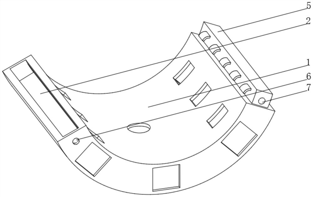
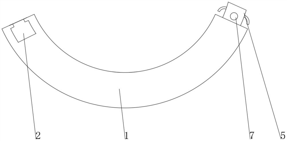
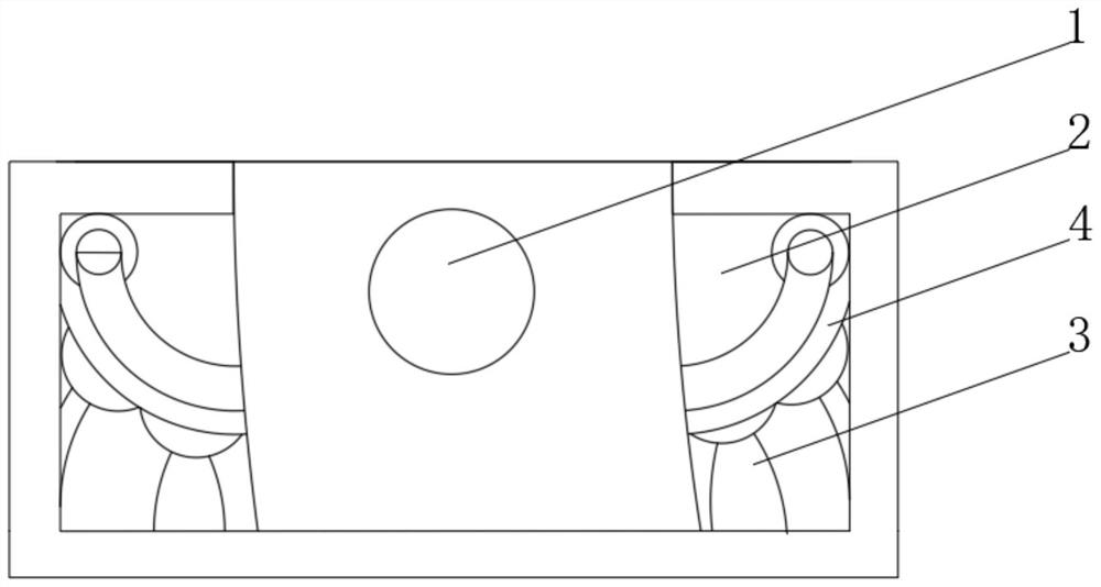
[0031] see Figure 1-4 , the present invention provides a technical solution: a shield segment, including a segment body 1, one end of the segment body 1 is provided with a mounting groove 2, the bottom of the inner wall of the mounting groove 2 is fixedly connected with a support rod 3, and the inner wall of the mounting groove 2 is a There is an air hole 6 on the side, the top of the support rod 3 is fixedly connected with an arc-shaped support plate 4, and the end of the segment body 1 away from the installation groove 2 is fixedly connected with a chuck 5, and the side of the chuck 5 is provided with an air nozzle 7, and the chuck 5 Including the chuck body 51, both sides of the chuck body 51 are provided with a chuck groove 52, the bottom of the inner wall of the chuck groove 52 is fixedly connected with a fixing seat 53, and both sides of the top of the fixing seat 53 are rotatably connected with an arc spring 54. The top of the spring 54 is rotatably connected with a ro...

Embodiment 2

[0034] see Figure 1-5On the basis of Embodiment 1, the present invention provides a technical solution: the rotating clamp 55 includes a clamp body 551, one end of the clamp body 551 is provided with an arc-shaped groove 552, and the bottom of both sides of the inner wall of the arc-shaped groove 552 is fixedly connected with Spring piece 553, the end of spring piece 553 away from arc groove 552 is connected with arc rod 554 in rotation, the end of arc rod 554 away from spring piece 553 is connected with roller 555 through rotation bolt rotation, and the bottom of clamp body 551 is fixedly connected with reinforcement Block 556, the reinforcing block 556 is fixedly connected with an arc-shaped reinforcing bar 557 on one side away from the clamp body 551, and is provided with an arc-shaped rod 554 and a spring leaf 553. The inside of 551 shrinks, which can avoid the failure of installation caused by the dimensional error between the installation groove 2 and the rotating clamp...


PUM


Abstract

The invention discloses a shield segment, and relates to the technical field of buildings. The shield segment comprises a segment body, a mounting groove is formed in one end of the segment body, a supporting rod is fixedly connected to the bottom of the inner wall of the mounting groove, an air hole is formed in one side of the inner wall of the mounting groove, an arc-shaped supporting plate is fixedly connected to the top of the supporting rod, and a clamping head is fixedly connected to the end, away from the mounting groove, of the segment body. An air nozzle is formed in one side of the clamping head, the position of the air nozzle on the clamping head is matched with the position of the air hole in the mounting groove, an arc-shaped supporting seat is arranged between the supporting rod and the arc-shaped supporting plate, a clamping head body is fixedly connected with one end of the segment body, one end of a rotary clamping plate extends out of the clamping head groove, and the end, located outside the clamping head groove, of the rotary clamping plate is arranged to be in an arc shape. According to the shield segment, the strength of the joint is higher, the safety is better, the connection between the segments is more stable, the use is safe and reliable, the segments are convenient to separate, and the disassembly and the assembly are simpler.

Description

technical field [0001] The invention relates to the technical field of building construction, in particular to a shield segment. Background technique [0002] There are usually several construction methods involved in tunnel excavation in modern construction projects, including open-cut method and concealed excavation method. Among them, the shield method in the concealed method is a fully mechanized construction method. The method has the advantages of safe excavation and does not affect the facilities on the ground, and is widely used in tunnel construction, such as: railway tunnels, highway tunnels, underwater tunnels, underground railways, etc. [0003] At present, the shield segments used in the shield tunneling method usually have poor connection stability. During pre-assembly, the segments are prone to slipping and falling off, which is inconvenient to use, and the strength of the connection is low, which affects the safety of use. . Contents of the invention [0...

Claims


Application Information

Patent Timeline
IPC IPC(8): E21D11/08
CPCE21D11/08E21D11/083
Inventor 徐洪舟
Owner 杨明勇
Why Eureka
Try Eureka