Numerical control pressure relief valve bank

A technology of pressure relief valve and hydraulic control check valve, which is applied in servo motor components, fluid pressure actuators, mechanical equipment, etc., can solve the problems of low pressure relief efficiency and high pressure, and achieve the effect of improving pressure relief efficiency

Active Publication Date: 2021-04-09
ZHENGZHOU RES INST FOR ABRASIVES & GRINDING CO LTD
View PDF6 Cites 0 Cited by
  • Summary
  • Abstract
  • Description
  • Claims
  • Application Information

AI Technical Summary

Problems solved by technology

[0005] This device is used to provide stable linear pressure relief. By continuously opening and closing the upper pressure relief device, the pressure relief oil is discharged into the metering device. At the same time, because the volume of the metering device is fixed, the lower pressure relief device is opened and the upper pressure relief device is closed. At this time, the fixed volume of pressure relief oil is discharged, so a stable linear pressure relief can be provided. Since the pressure in the initial pressure relief stage is large, in order to stabilize the pressure relief, the oil flowing out each time the pressure relief cannot be too much, but In the late stage of pressure relief, due to the decrease in pressure, the pressure relief oil can be discharged faster, however, the volume of the metering device is fixed, the amount of oil discharged each time is fixed, and the pressure relief provided is linear, so in the relief In the second half of the pressure process, the pressure relief efficiency is low

Method used


Image

  • Numerical control pressure relief valve bank
  • Numerical control pressure relief valve bank
  • Numerical control pressure relief valve bank

Examples


Embodiment Construction

[0018] The following will clearly and completely describe the technical solutions in the embodiments of the present invention with reference to the drawings in the embodiments of the present invention. Based on the embodiments of the present invention, all other embodiments obtained by persons of ordinary skill in the art without making creative efforts belong to the protection scope of the present invention.

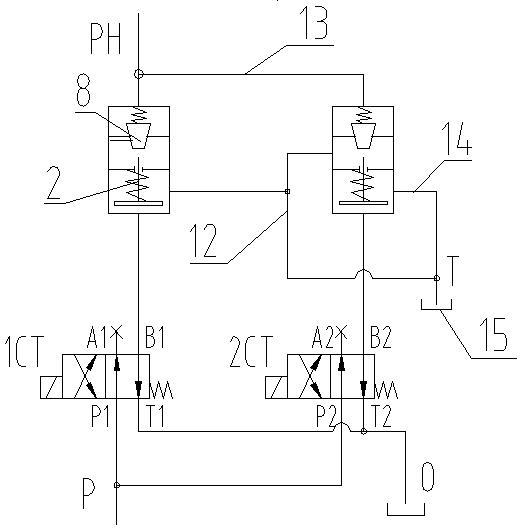
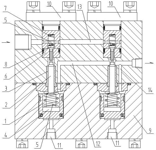
[0019] Such as figure 1 , figure 2 As shown, the present invention includes two sets of ultra-high pressure hydraulic control check valves with the same structure. The ultra-high pressure hydraulic control check valve includes an oil inlet and an oil outlet, that is, the oil inlet includes an oil inlet chamber 5 Cone valve 6 and spring 7, the cone valve 6 is provided with an oil guide groove, the oil outlet part includes a cavity 1, a piston ejector rod 2, a ejector rod bushing 3, and a piston 4, and the oil inlet part It communicates with the oil outlet, the ejecto...


PUM


Abstract

The invention aims to provide an ultrahigh-pressure numerical control pressure relief valve bank which is used for improving the pressure relief efficiency. The ultrahigh-pressure numerical control pressure relief valve bank comprises two sets of ultrahigh-pressure hydraulic control one-way valves with the same structure, and pressure relief oil outlets of the two sets of ultrahigh-pressure hydraulic control one-way valves are different in damping and used for releasing pressure of different pressure sections. Oil inlet parts of the two sets of ultrahigh-pressure hydraulic control one-way valves with the same structure are connected in parallel, an oil outlet part of one set of ultrahigh-pressure hydraulic control one-way valve communicates with a gap between a piston ejector rod and a valve element of the other set of ultrahigh-pressure hydraulic control one-way valve, and then the gap communicates with an oil tank; meanwhile, an oil outlet part of the other set of ultrahigh-pressure hydraulic control one-way valve communicates with the oil tank through a pipeline to form a pressure relief valve bank, in the initial pressure relief stage, the ultrahigh-pressure hydraulic control one-way valve with large damping is used for pressure relief, and in the later stage of pressure relief, the ultrahigh-pressure hydraulic control one-way valve with small damping is used for pressure relief, so that the pressure relief efficiency is improved; and at the same time, a programmable logic controller (PLC) is introduced to operate an electromagnetic reversing valve, and automatic operation of the whole pressure relief process can be achieved through a set time table.

Description

technical field [0001] The invention belongs to the technical field of ultra-high pressure pressure relief, and in particular relates to an ultra-high pressure numerically controlled pressure relief valve group. Background technique [0002] At present, the synthesis equipment of synthetic diamond in our country is a six-sided top press, which adopts an ultra-high pressure hydraulic system with an oil pressure of up to 110MPa. Its ultra-high pressure oil pump or reciprocating supercharger can directly output oil pressure up to 110MPa to the working cylinder of the six-sided top press. After the pressing work of the press is completed, it needs to be released from the ultra-high pressure pipeline to reduce the pressure. [0003] A patent document with the patent number CN110354762A discloses a metering discharge device, which includes two upper and lower pressure relief devices and an eccentric shaft for opening and closing the upper and lower pressure relief devices respecti...

Claims


Application Information

Patent Timeline
Patent Type & Authority Applications(China)
IPC IPC(8): F15B13/02
CPCF15B13/027F15B13/024
Inventor 古龙辉祁路方司少鹏闫宁陈亦工
Owner ZHENGZHOU RES INST FOR ABRASIVES & GRINDING CO LTD
Why Eureka
Try Eureka