
Double-rail equipment capable of automatically advancing and adjusting distance

A technology to adjust the spacing and double rails, which is applied in the field of guide rails, and can solve the problems of unable to adjust the spacing of guide rails, unable to be widely used, and cumbersome devices.

Inactive Publication Date: 2021-04-09
南京亿拉尔科技有限公司
View PDF0 Cites 0 Cited by
  • Summary
  • Abstract
  • Description
  • Claims
  • Application Information

AI Technical Summary

Problems solved by technology

[0002] Guide rails, also known as slide rails, linear guide rails, linear slide rails, are grooves or ridges made of metal or other materials, which can withstand, fix, guide mobile devices or equipment and reduce their friction. The longitudinal groove on the surface of the guide rail Or ridges, used to guide and fix machine parts, special equipment, instruments, etc., used in linear reciprocating motion occasions, have a higher rated load than linear bearings, and can bear a certain torque at the same time, which can be realized under high load conditions High-precision linear motion, but the guide rail is generally fixed, and the distance between the guide rails cannot be adjusted, so it can only be installed with objects of limited width, which cannot be widely used, and the guide rail cannot be moved actively, and an external driving force is required to make it move, which makes installation on the guide rail The device on the device is too cumbersome

Method used


Image

  • Double-rail equipment capable of automatically advancing and adjusting distance
  • Double-rail equipment capable of automatically advancing and adjusting distance
  • Double-rail equipment capable of automatically advancing and adjusting distance

Examples


Embodiment Construction

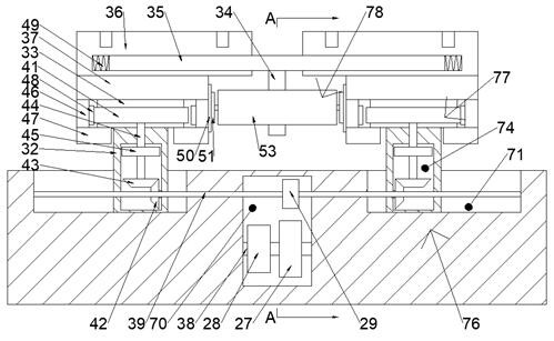
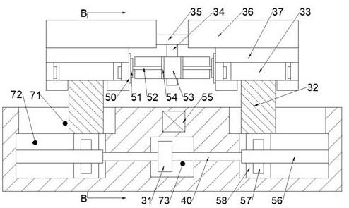
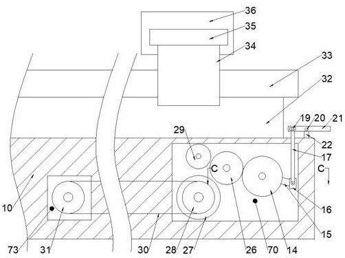
[0019] Combine below Figure 1-5 The present invention is described in detail, wherein, for the convenience of description, the orientations mentioned below are defined as follows: figure 1 The up, down, left, right, front and back directions of the projection relationship itself are the same.

[0020] A double-track equipment capable of automatically advancing and adjusting the distance of the device of the present invention includes a body 10, a power chamber 70 is provided in the body 10, a pulley chamber 73 is provided on the rear side of the power chamber 70, and a pulley chamber 73 is arranged on the body 10. There are two left and right symmetrical sliding chambers 71 on the side, and the lower side of the sliding chamber 71 is provided with a threaded chamber 72. The sliding chambers 71 are respectively slidably connected with guide rail plates 32, and the guide rail plates 32 are provided with transmission chambers 74. and a plurality of connection chambers 75, the u...


PUM


Abstract

The invention discloses double-rail equipment capable of automatically advancing and adjusting distance. The double-track equipment comprises a machine body. A power cavity is formed in the machine body, a belt wheel cavity is formed in the rear side of the power cavity, two sliding cavities which are symmetrical left and right are formed in the upper side of the machine body, threaded cavities are formed in the lower sides of the sliding cavities, guide rail plates are slidably connected into the sliding cavities correspondingly, a transmission cavity and a plurality of connecting cavities are formed in the guide rail plates, horizontal guide rails are fixedly arranged on the upper sides of the guide rail plates, a main motor is arranged on the left side wall of the power cavity and is in power connection with a motor shaft, an air pump is fixedly arranged on the upper side of the machine body, a moving device for changing the distance between the guide rails is arranged in the machine body, guide rail devices capable of moving automatically are arranged on the upper sides of the sliding cavities, and a control device for controlling the moving direction is arranged on the upper side of the machine body. The equipment can freely control the distance between the guide rails and the movement of the guide rails, the guide rails are more convenient to use, guide rail built-in drivers enable the whole equipment outside the guide rails to be neater, and control operation is convenient.

Description

technical field [0001] The invention relates to the related field of guide rails, in particular to a double-rail device capable of automatically advancing and adjusting the spacing. Background technique [0002] Guide rails, also known as slide rails, linear guide rails, linear slide rails, are grooves or ridges made of metal or other materials, which can withstand, fix, guide mobile devices or equipment and reduce their friction. The longitudinal groove on the surface of the guide rail Or ridges, used to guide and fix machine parts, special equipment, instruments, etc., used in linear reciprocating motion occasions, have a higher rated load than linear bearings, and can bear a certain torque at the same time, which can be realized under high load conditions High-precision linear motion, but the guide rail is generally fixed, and the distance between the guide rails cannot be adjusted, so it can only be installed with objects of limited width, which cannot be widely used, an...

Claims


Application Information

Patent Timeline
IPC IPC(8): F16C29/12
CPCF16C29/12
Inventor 王许
Owner 南京亿拉尔科技有限公司
Learn More