Novel radiator structure

A new type of radiator and heat dissipation fin technology, which is applied in the fields of instruments, chemical instruments and methods, and electrical digital data processing, etc., can solve the problems of poor heat dissipation performance, no cleaning function, and low heat dissipation efficiency of radiators, and achieve wind Good cooling and heat dissipation effect, speed up the air flow speed, and increase the range of blowing heat dissipation

Pending Publication Date: 2021-04-09
诸暨市泰源供暖设备有限公司
View PDF0 Cites 3 Cited by
  • Summary
  • Abstract
  • Description
  • Claims
  • Application Information

AI Technical Summary

Problems solved by technology

[0005] Aiming at the deficiencies of the prior art, the present invention provides a new type of radiator structure, which solves the problem that the existing radiator has a simple structure, usually only a plurality of heat dissipation fins are used to absorb and transmit heat for heat dissipation, and the heat dissipation effect is not good. The heat dissipation efficiency is low, resulting in poor heat dissipation performance of the radiator, the use effect of the radiator is not ideal, and it does not have the function of cleaning the surface of the heat dissipation fins on the radiator. When the radiator is used for a long time, the dust accumulated on the surface of the heat dissipation fins More and more, which will affect the heat dissipation effect of the radiator

Method used


Image

  • Novel radiator structure
  • Novel radiator structure
  • Novel radiator structure

Examples


Embodiment Construction

[0028] The following will clearly and completely describe the technical solutions in the embodiments of the present invention with reference to the accompanying drawings in the embodiments of the present invention. Obviously, the described embodiments are only some, not all, embodiments of the present invention. Based on the embodiments of the present invention, all other embodiments obtained by persons of ordinary skill in the art without making creative efforts belong to the protection scope of the present invention.

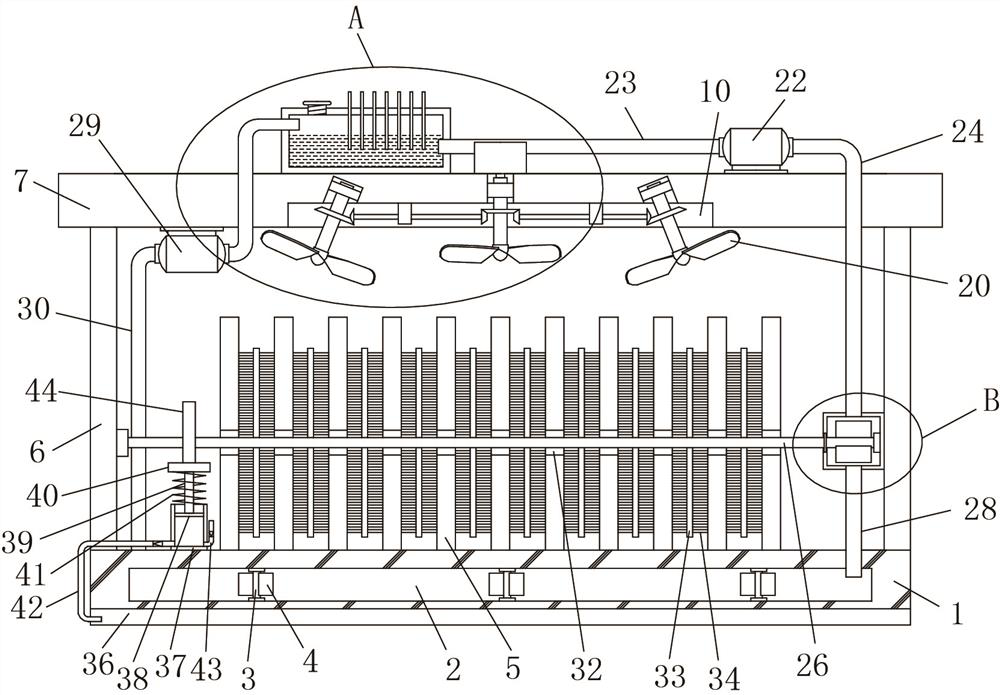
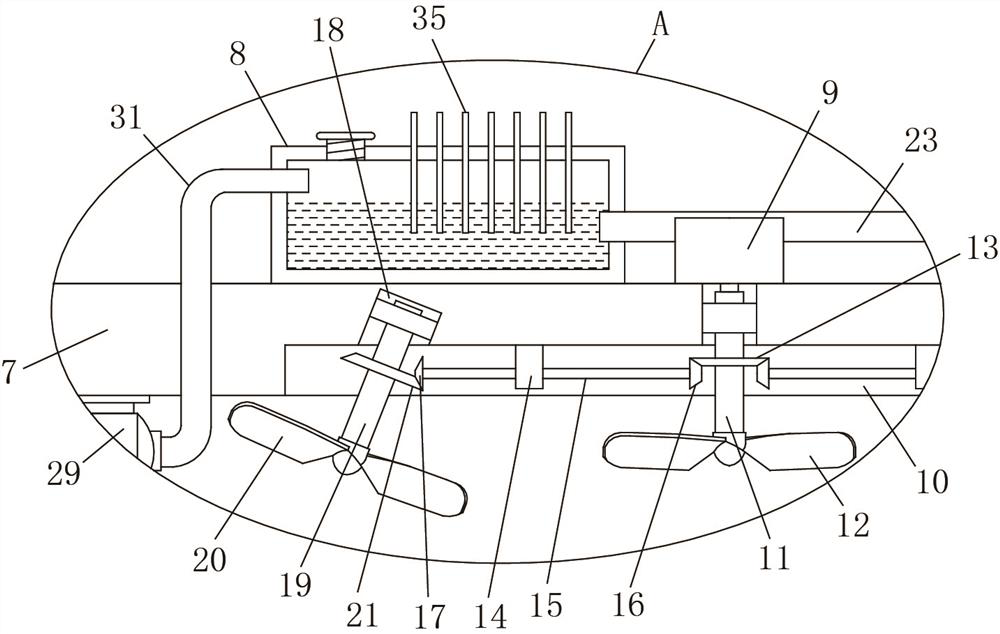
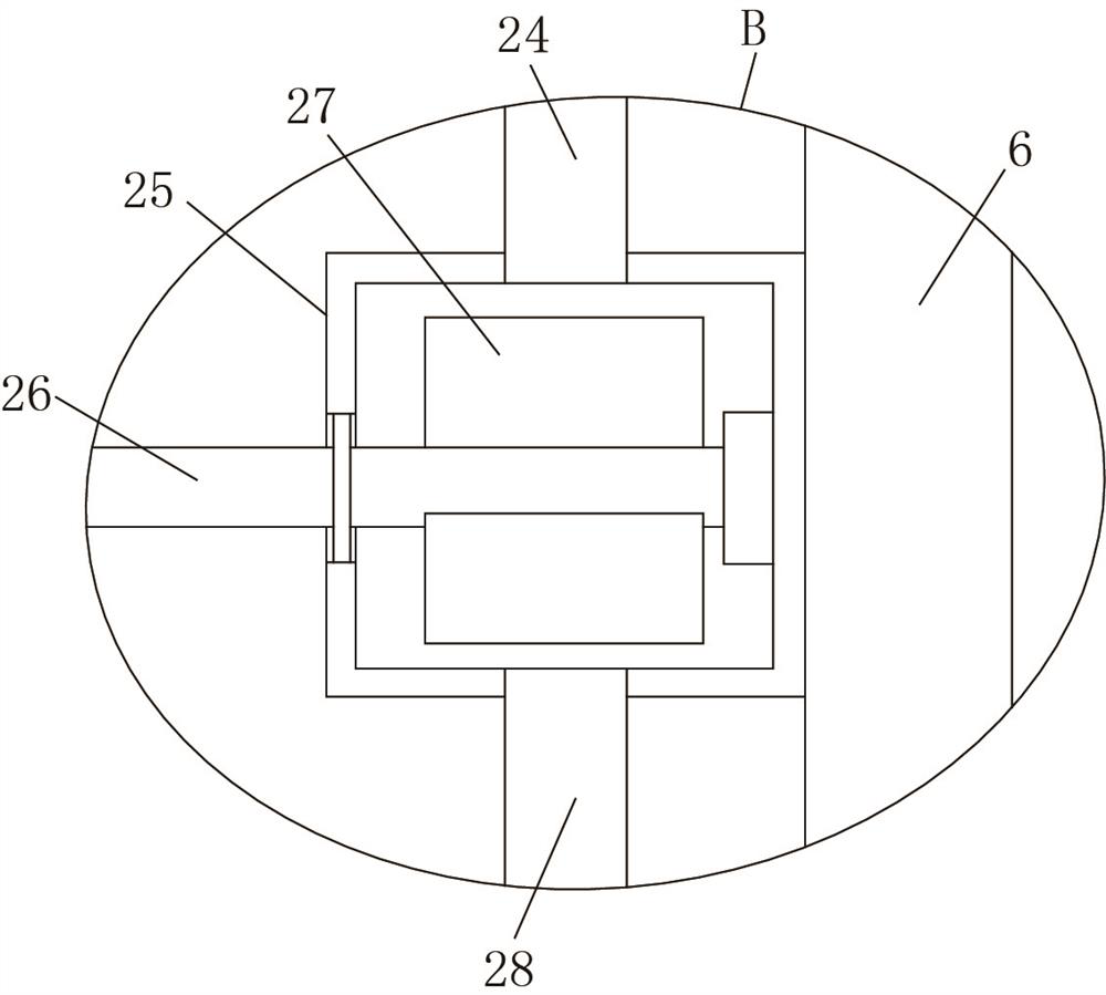
[0029] Such as Figure 1-6 As shown, the present invention provides a technical solution: a novel radiator structure, including a heat conduction plate 1, an S-shaped cavity 2 is opened in the heat conduction plate 1, six rotating shafts 3 are arranged in the S-shaped cavity 2, and six rotating shafts 3 It is symmetrically arranged in pairs, and the first arc-shaped blades 4 are fixedly installed on the six rotating shafts 3, and a plurality of first cooling fin...


PUM


Abstract

The invention discloses a novel radiator structure which comprises a heat conduction plate, an S-shaped cavity is formed in the heat conduction plate, six rotating shafts are arranged in the S-shaped cavity, every two of the six rotating shafts are symmetrically arranged, first arc-shaped blades are fixedly installed on the six rotating shafts, and a plurality of first radiating fins are fixedly installed at the top of the heat conduction plate at equal intervals. Two stand columns are fixedly installed at the top of the heat conduction plate, the same transverse plate is fixedly installed at the top ends of the two stand columns, and a liquid storage tank and a motor are fixedly installed at the top of the transverse plate. The novel radiator structure is reasonable in design and good in practicability, heat generated by a CPU is absorbed through the heat conduction plate and the multiple first heat dissipation fins, efficient heat dissipation can be achieved through air cooling heat dissipation and water cooling heat dissipation, the heat dissipation effect and heat dissipation efficiency are improved, the heat dissipation performance is enhanced, the surfaces of the multiple first heat dissipation fins can be effectively cleaned, and the dust is prevented from being gathered on the plurality of first heat dissipation fins to influence the heat dissipation effect.

Description

technical field [0001] The invention relates to the technical field of radiators, in particular to a novel radiator structure. Background technique [0002] Radiator is a general term for a series of devices used to conduct and release heat. At present, radiators mainly include heating radiators and computer radiators. Among them, radiators can be divided into several types according to materials and working modes. One of the commonly used radiators. With the rapid development and progress of science and technology, the use of computers is becoming more and more common. The use of computers brings convenience to people's life and work. CPU is the computing and control core of computer systems. It is the final execution unit of information processing and program operation. The operating temperature of the CPU is related to the stability and service life of the computer. To keep the operating temperature of the CPU within a reasonable range, in addition to reducing the working...

Claims


Application Information

Patent Timeline
IPC IPC(8): G06F1/20B08B1/00B08B1/04B08B5/02
CPCG06F1/20B08B5/02B08B1/12B08B1/32
Inventor 陈建陈军
Owner 诸暨市泰源供暖设备有限公司
Why Eureka
Try Eureka